
DQE Series Safety Light Curtain Sensor and Safety Relay Connection Guide
The main link between safety light curtains and safety relays in the modern industrial automation system, and the reliable safety, is vital to the safe function of human and equipment. As such these safety light curtains are used extensively in stamping, machining, automated assembly line, etc in various situations.
Safety-output type, diagnostic pulse compatibility and protective capability must be confirmed for the exact order code; they cannot be assumed across the full catalog. This guide discusses DAIDISIKE DQE Series Safety Light Curtains are broadly used such as in stamping, machining, automated assembly lines, and other applications. We have detailed in this article the connection principle and we will take a brief step in each step, examples, and key consideration of both the DQE series safety light curtains and safety relays. It explains the engineering checks, not a pre-approved machine circuit.
Content updated: . This model-level guide belongs to the light curtain installation and wiring index; the broader diagram library covers other interfaces. Keep actual terminal assignments separate from these functional explanations.
How to Connect a Light Curtain Safety Relay
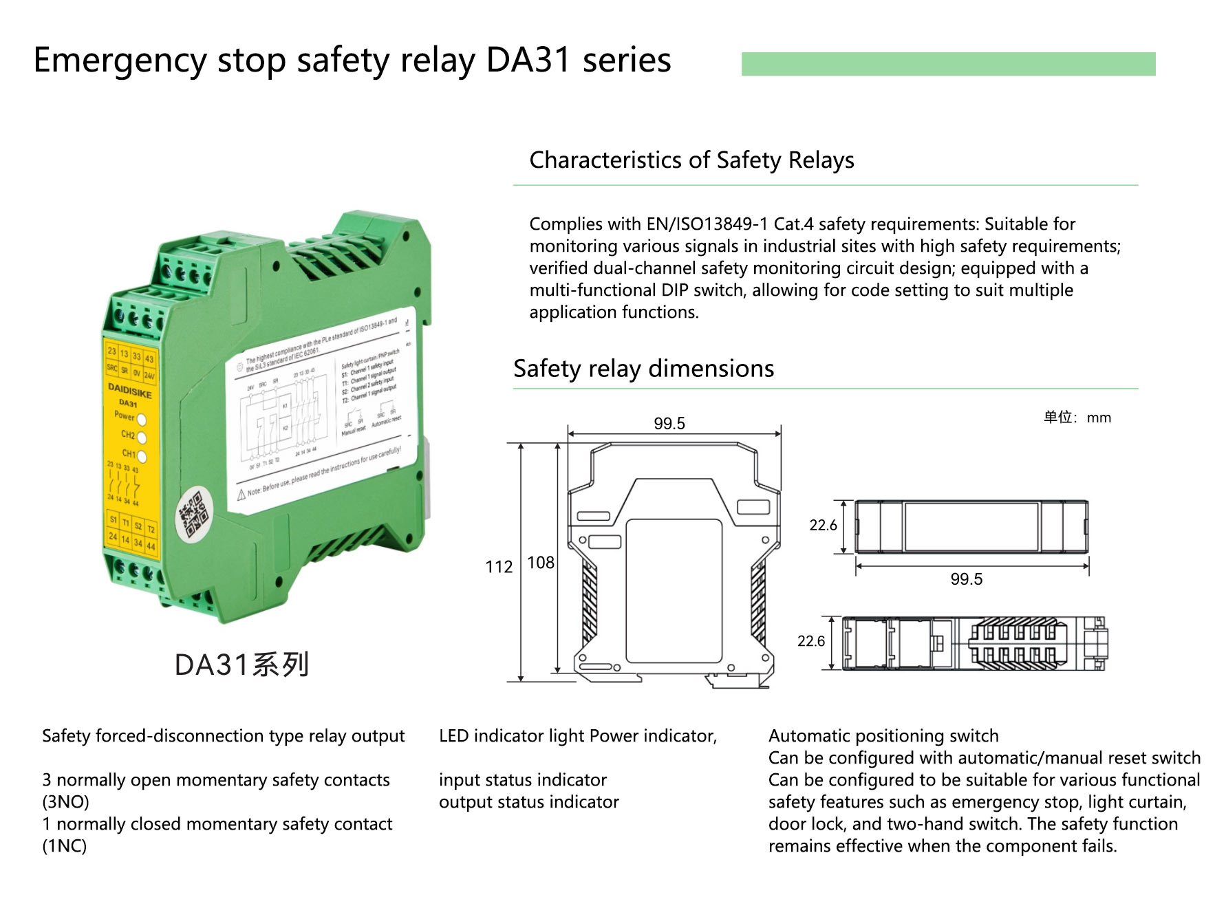
The functional signal path is: Light Curtain OSSD1/OSSD2 → Safety Relay → Contactors/STO → Machine Stop. The selected relay must accept the exact light curtain's documented OSSD signals, and the complete stop circuit must be designed and validated for the machine. Compare the documented models before wiring: both DA31 and DQSRN are safety relay modules, but their reset and feedback functions are different.
| Selection point | DA31 | DQSRN |
|---|---|---|
| Module type | Safety relay module | Safety relay module |
| Dual OSSD connection | Use only when compatibility is confirmed by the exact manuals | Use only when compatibility is confirmed by the exact manuals |
| Manual / automatic reset | Provided as documented for DA31 | Not provided |
| EDM feedback | Not stated in current factory material; request the exact manual or select a controller with documented EDM | Not provided |
For product selection before drawing the circuit, you can compare safety relay modules for light curtains. A standard delay relay cannot replace a safety relay in the protective stop function.
I. Principles and Prerequisites of Connectivity core.
This DQE example uses two OSSD (Output Signal Switching Device) outputs. Confirm the exact model's output type and published safety classification from its current manual; this page does not assign DQE a Type 2 or Type 4 classification. Safety relays such as DA31 and DQSRN accept only the curtain signals documented as compatible in the exact manuals. The selected relay switches the validated machine-stop circuit. Reset and EDM functions are model-specific. DA31 documents manual/automatic reset selection but not EDM feedback; DQSRN provides neither function.
2.2.2 Connection Requirement
Check that the safety relay and the complete circuit meet the required safety level established by the machine risk assessment; do not infer a Type 2 or Type 4 classification for DQE from this connection example. Confirm that the DQE output type (NPN/PNP) is compatible with the safety relay input. Design and configure cables, protection, supply tolerance, mounting clearance and EMC measures according to the exact sensor and relay instructions. Do not apply a universal 5 A fuse, 50 mm clearance, conductor size or power-supply tolerance to every model.
II. General Wiring Process (dual OSSD, with DA31 reset selection)
1. Preparation before wiring
Isolate hazardous energy and verify the safe condition before wiring. The owner-confirmed DQE reference identifies white as OSSD1 and black as OSSD2; verify the delivered cable revision, supply, earthing and all terminal labels against its actual manual. Use the relay mounting and clearance specified for the supplied module, not a universal 5 cm rule.
Sensor: documented protective OSSD1 and OSSD2, each evaluated on its own compatible safety-input channel.
Safety logic: selected relay/controller with verified input diagnostics and the reset/feedback functions actually required.
Final elements: validated contactor or drive safety interface; feedback is evaluated only by a controller that supports it.
Machine: measured stopping performance and safeguards for every access path.
Step-by-step wiring
(1) Power connection Verify supply voltage, permitted ripple, polarity, current demand and protective devices against both manuals. Use the specified supply and grounding arrangement. Brown and blue identification in this DQE reference is not a universal fuse rating or permission to share any power circuit.
(2) The OSSD signal connection (dual redundancy) Route the DQE white line (OSSD1) and black line (OSSD2) to the two safety inputs identified in the selected relay's exact manual. S1/S2 and CP are shown in the DQSRN example; do not transfer those terminal labels to DA31 unless its delivered manual confirms them. Match NPN/PNP polarity exactly as documented for both devices.
(3) Verify reset and EDM requirements before wiring DA31 factory material documents an SRC/SR selector for manual or automatic reset, but it does not state an EDM feedback function or a T1/T2 EDM path. DQSRN provides neither reset nor EDM. If the machine safety design requires contactor feedback, obtain an exact current manual that explicitly confirms EDM or select a controller that documents the function. Do not create a T1/T2 loop from an unrelated diagram.
(4) DA31-only reset function connection Configure the SRC/SR selector for manual or automatic reset exactly as shown in the delivered DA31 manual and as required by the machine risk assessment. Do not infer the selector state from this overview. DQSRN provides neither manual nor automatic reset, so this step does not apply to it.
(5) Shield and ground Distinguish protective earth from cable shield termination. Follow the specified conductor identification, bonding, cable routing and shield terminations in the sensor, relay and drive manuals. Neither single-ended grounding, a 4 ohm resistance nor a 200 mm cable spacing is a universal instruction for this combination.
Sample Connection (DAIDISIKE Safety Relay Adapted)
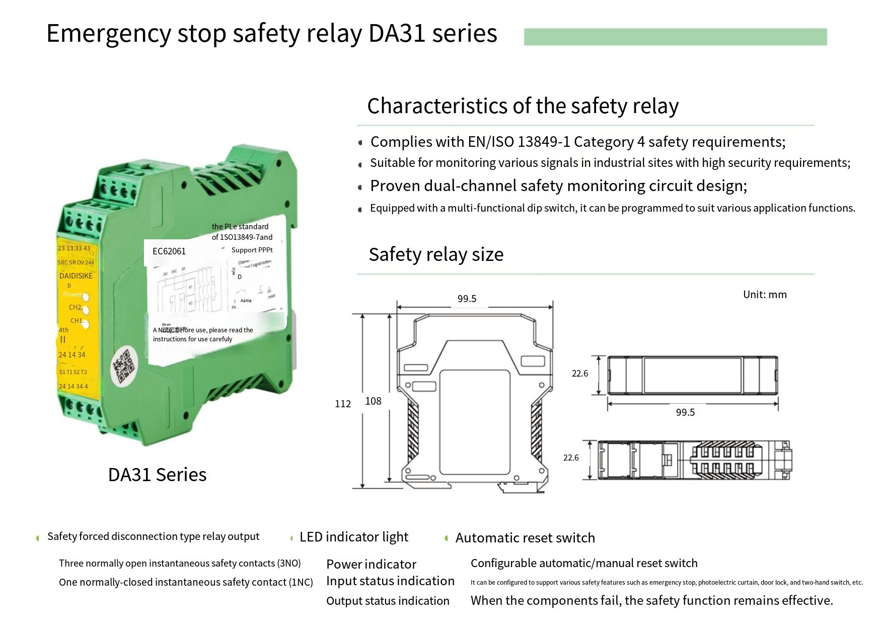
Example 1: DQE series (PNP type) + DA31 series safety relay
| DQE light curtain cable | Function | DA31 connection point (confirm exact manual) | Note |
|---|---|---|---|
| brown | +24VDC | 24 V DC supply terminal per manual | Use the manufacturer-specified protection and conductor rating |
| Blue | 0V | 0 V supply terminal per manual | Power supply common ground |
| White (OSSD1) | Safety output 1 | Safety input channel 1 (terminal per manual) | Dual inputs need to be connected at the same time |
| Black (OSSD2) | Safety output 2 | Safety input channel 2 (terminal per manual) | |
| Yellow-green | Protective earth/shield identification — verify exact cable | Grounding point per manual | Shield termination and protective earth are different; follow both manuals |
| Reset button | Manual / automatic reset selection | SR + SRC | Configure only from the exact DA31 manual |
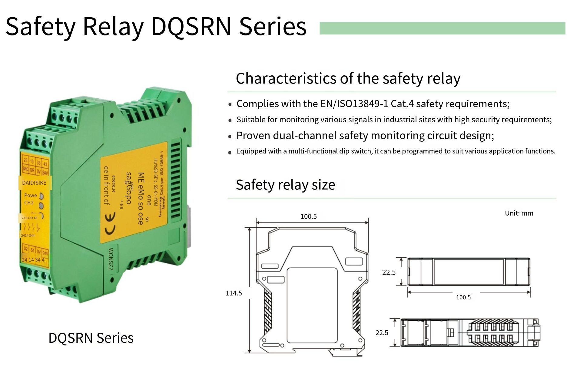
Example 2: DQE series (NPN type) + DQSRN series safety relay (2 outputs)
DQSRN accepts the documented OSSD input pair, but it does not provide manual reset, automatic reset or EDM feedback. Do not copy the DA31 SRC/SR reset wiring into this example, and do not add a T1/T2 EDM loop to either relay from an unrelated diagram. If the safety function requires monitored reset or contactor feedback, select a controller that explicitly provides those functions.
Verify the supplied DQSRN manual before assigning its supply, CP, safety inputs or output contact pairs. Do not transpose DA31 terminal names or copy the legacy 23/14 and 33/43 pairs: the final switching arrangement must use the actual module contact diagram. Confirm output count, NO/NC purpose, switching load and protective function rather than assuming an NC status contact is a safety output.
Need More Than Four Outputs? Custom Programmable Safety Control Projects
Some machines need more controlled output circuits than a standard safety relay provides. For qualified volume projects, DAIDISIKE can evaluate an engineering-to-order, PLC-programmable multi-output safety control architecture with five, six, seven, eight or more project-defined output circuits.
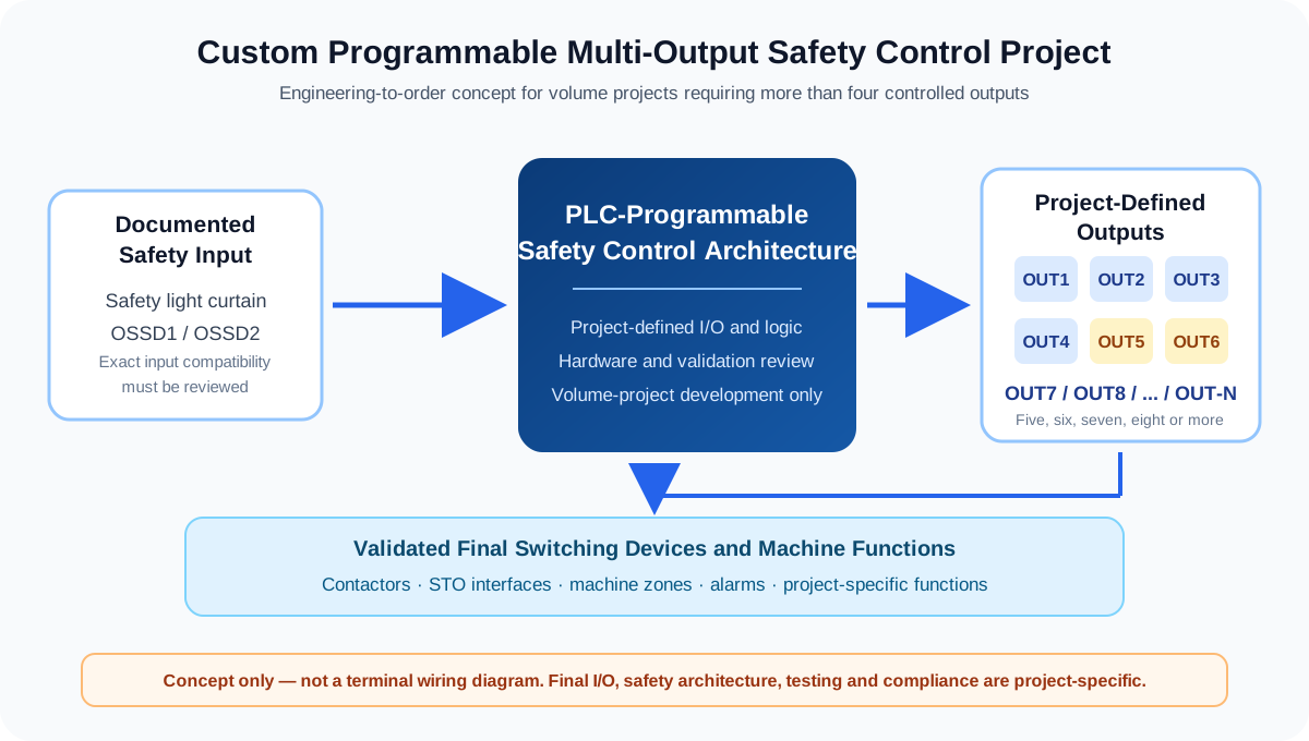
What Can Be Evaluated for a Volume Project?
- Five, six, seven, eight or more project-defined output circuits.
- PLC-programmable logic based on an approved machine I/O matrix.
- Project-specific hardware, enclosure and output architecture.
- Integration requirements for documented safety inputs and final switching devices.
- Prototype, functional testing and required compliance evidence defined in the project plan.
Information Required for a Custom Evaluation
| Project information | What the engineering team needs |
|---|---|
| Safety inputs | Exact light curtain, E-stop, guard-switch or other device models and output types. |
| Required outputs | Number of circuits, whether they act together or independently, and the required safe state. |
| Loads and interfaces | Contactor coils, STO interfaces, machine-control inputs, voltage and current requirements. |
| Control logic | Sequence, reset, feedback, diagnostics and fault-response requirements. |
| Risk and compliance | Machine risk assessment, target standards and evidence required by the destination market. |
| Commercial scope | Estimated project quantity, development schedule and validation responsibilities. |
Have a volume project that needs more than four outputs? Send the machine I/O list, required logic, destination market and estimated quantity for an engineering feasibility review.
Request a Custom Project EvaluationCheck Before Power-on
Compare every conductor and terminal with the released project drawing and exact equipment instructions. Check isolation, shorts, polarity, permitted supply range, protective earth and shielding before energising. A multimeter continuity test does not validate OSSD pulse compatibility or the safety function.
Functional debugging
With hazardous motion prevented, verify the documented clear-field and interrupted-field output states. Do not assume a high output for every polarity or describe a normal protective trip as channels becoming out of step. Test both protective input channels and the resulting final-element response using the manufacturer-approved procedure; actual machine motion takes the measured system stopping time to cease. For a DA31 installation, test the selected reset mode exactly as its manual specifies; do not perform an EDM test unless an exact current manual explicitly documents that function. For DQSRN, stop after validating its documented OSSD trip and output behaviour: DQSRN has no reset or EDM function to test.
When adding PLC diagnostics after the protective circuit is defined, compare the Mitsubishi FX5U auxiliary-status mapping and standard Siemens S7-1200 diagnostic interface checks. These DQC examples keep ordinary PLC status separate from safety evaluation; they do not establish DQE/DA31 compatibility or add reset/EDM functions to a relay.
Historical owner confirmation on August 13, 2026 covered the DQE white/black conductor mapping, not an independent review of every circuit or current product capability on this page.
DAIDISIKE Tech & Video Center
Advanced Sensor Solutions for Industrial Safety and Automation
DAIDISIKE Corporate Profile
Discover our commitment to precision engineering and manufacturing.
Safety Interlock DX Series
Real-world application for advanced machine safeguarding.
AGV LiDAR DLD30T-5N — 30 m at 90% remission / 10 m at 10% remission
Enhanced perimeter security and collision prevention solutions.
Vehicle DQLV Light Curtains
Optimized for toll stations and weighbridges profiling.
Measuring DQL Series 3D
Dimensional measurement and object positioning principles.
DQC Universal Grating
Installation guide for hand & finger safeguarding.
Waterproof DQR Series
Performance under high-pressure washdowns.
Color Mark Sensors
Intelligent recognition for high-speed packaging lines.
Strip DK-D461 Sensors
Advanced background suppression for irregular shapes.
Area DQSA Protection
Cost-effective side safeguarding using mirror reflection.
Frequently Asked Questions
How do I wire a safety light curtain to a safety relay?
Connect the curtain's two OSSD outputs to the safety relay's documented dual safety inputs, supply both devices as specified, and wire the safety outputs into the validated stop circuit. Reset and EDM are model-specific: DA31 documents an SRC/SR reset selector but its current material does not state EDM; DQSRN provides neither function.
What do I check before powering on?
Verify supply voltage and polarity, that both OSSD channels go to the correct relay inputs, and that the output switching circuit matches the exact manuals. Configure the DA31 SRC/SR reset selector only from its current manual. Do not add an EDM loop unless the selected controller's exact documentation explicitly provides one; DQSRN provides neither reset nor EDM.
Why use a safety relay instead of wiring directly?
An appropriate safety relay provides the documented switching and fault handling required by the validated circuit. EDM and controlled reset are not universal functions: DA31 documents reset selection but not EDM, while DQSRN provides neither. Wiring a curtain straight to a standard contactor does not by itself establish a validated safety function.
How do I test the wiring is correct?
With hazardous motion prevented, use the specified test piece to check clear-field and interrupted-field outputs across the protective field and its boundaries. Validate the complete stopping function separately under the manufacturer-approved controlled test procedure; never use a person entering the hazard as the test. For DA31, test the selected reset mode exactly as its manual specifies; do not perform an EDM test unless an exact current manual explicitly documents that function. For DQSRN, test only its documented input and output behaviour because it has no reset or EDM function. Record the results.
Does manual or automatic reset change the wiring?
Yes, where the selected controller provides reset terminals. The DA31 example uses its documented reset selector and must be configured from its manual and risk assessment. DQSRN does not provide manual reset or automatic reset, so this wiring does not apply to DQSRN.
Can DAIDISIKE customize a programmable safety control solution with more than four outputs?
DAIDISIKE can evaluate volume projects that require five, six, seven, eight or more project-defined output circuits. This is an engineering-to-order capability, not a standard catalog product. Final I/O, control logic, hardware architecture, validation, certification scope, development cost and minimum order quantity are confirmed only after technical review.