
Through-Beam or Single-Sided Reflective?
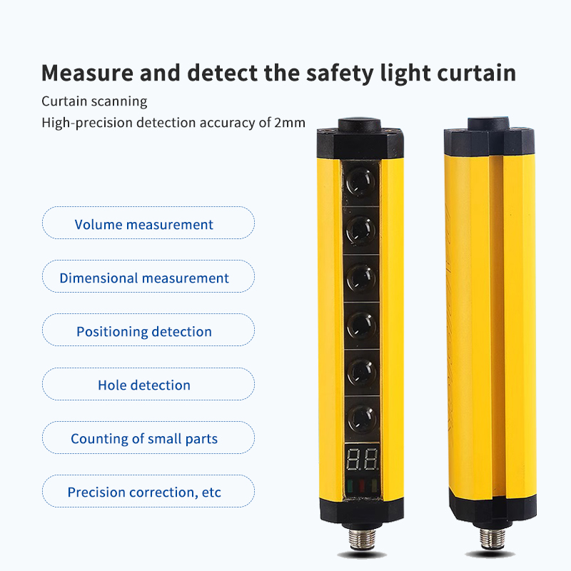
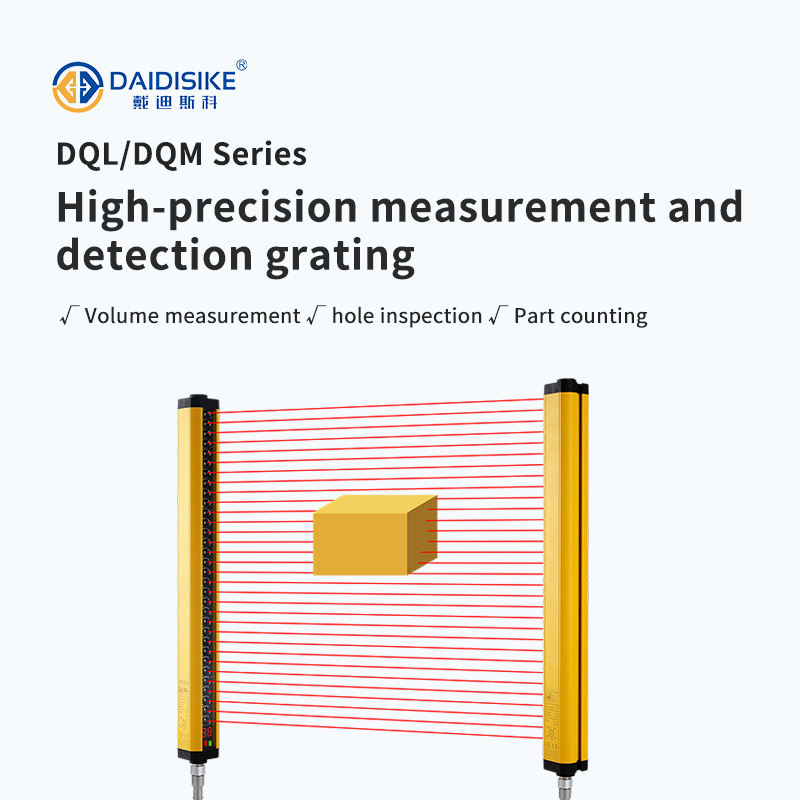
The DQL and DQM series are through-beam gratings: an emitter faces a receiver, so the object breaks a beam that is already established. That is what makes them repeatable enough for measurement and counting.
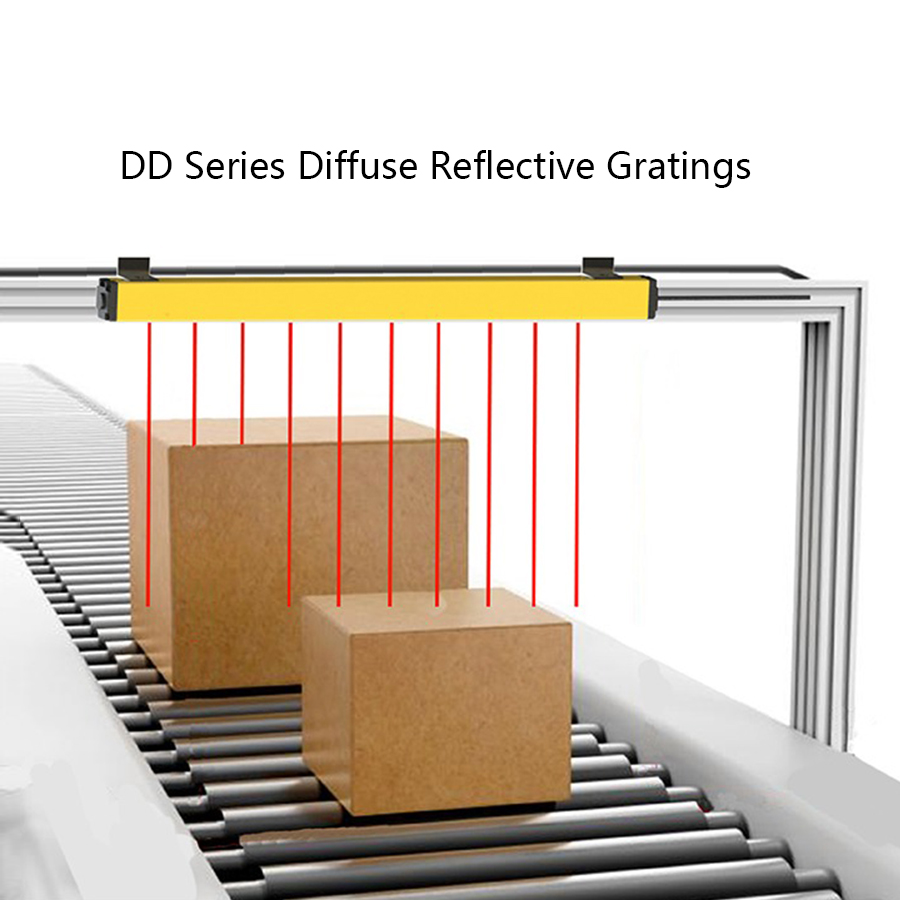
The DD series works from one side only — emitter and receiver share a single housing and the light returns from the object itself. You mount one profile instead of two and run one cable, which is why it suits doorways, conveyor edges and openings where a second column has nowhere to go. Two sensing principles are offered: diffuse reflection judges presence from returned light intensity (over 2000 mm, may have a blind zone), while the TOF version measures distance on each beam axis independently, reaching 4000 mm in the stated version. Verify minimum range, target reflectivity, background and ambient-light conditions in the exact manual; TOF is not universally unaffected by colour or surface finish.
Important: the DD series is a detection light grid. The factory manual states it is for area detection only and must not be used as a safety guarding device or for personnel protection. For guarding a press, a robot cell or any hazardous movement, use a through-beam safety light curtain instead.
Before selecting pitch and outputs, use the DQL/DQM measurement light curtain selection guide to define the dimensions or counts needed, target geometry and PLC data. These measurement products do not become personnel-protection devices by connecting them to a safety relay.
Dimension Measurement Light Curtain — Selection & Accuracy Guide (DAIDISIKE DQL/DQM)
Applies to DAIDISIKE DQL and DQM measurement & detection gratings. K is nominal beam pitch; H is the measuring span. Select both around the inspection task, then confirm the exact model's sensing and interface capabilities. This guide does not establish personnel-protection suitability or a safety rating.
- Define the smallest feature to detect. Specify the smallest opaque feature or opening, required measurement tolerance, object position and worst-case travel speed.
- Select and validate beam pitch K. Use K as beam-center spacing, not an accuracy guarantee. Confirm minimum detectable object or opening for the exact model and mode, then test representative samples.
- Size the measuring height H. Use H = (n - 1) × K for the published outer-beam-center span. Cover the full target envelope with application-specific margins and confirm the overall length from the order drawing.
- Verify detection and acquisition timing. Compare actual object and gap presence times with the configured sensor requirements. Separately allow for output, filtering, communication and PLC acquisition delays.
- Confirm the required output. Use DQL's model-specific serial or analog interface for measurement data, or DQM's NPN or PNP transistor output for high-speed detection/counting. DQM has no RS485 or RS232 interface. Confirm the selected output function and wiring before ordering.
1) Beam Pitch K vs. Minimum Detectable Size
Definition. K is the distance between adjacent beam centers in millimeters. Finer pitch samples the object more densely, but pitch, minimum detectable object, edge resolution and measurement accuracy are different specifications.
Feature check. There is no verified universal 1.2 × K object rule or 1.5 × K hole rule for these families. Ask for the exact model's detectable object and opening limits at the specified range and scan mode. Test the smallest target at different positions between beams, including expected vibration, alignment variation and material transparency. For gauging, compare repeated results with a reference measurement across the required working range.
The published DQL specification tables list K = 1.25, 2.5, 5, 10, 20, 40 and 80 mm; the DQM specification tables list 2.5, 5, 10, 20, 40 and 80 mm. Verify availability for the selected beam count. As a terminology example, Banner's EZ-ARRAY overview lists object detection and edge resolution separately; its values are not DQL/DQM ratings.
2) How to Size Measuring Height H
Measuring height must cover the target envelope along the array, including changes in object position and the installation tolerances. Set the margins from that application; one beam pitch at each end is not a universal allowance.
Beam-span formula. The published tables use H = (n − 1) × K, where n is beam count. This is the span between the first and last beam centers, not the transmitter-to-receiver range or overall housing length. For example, 32 beams at 2.5 mm pitch give H = 77.5 mm.
Select an available beam count that covers the required span, then check end offsets, mounting and connector clearance on the exact order drawing. The drawing below uses L = H + P + J + 30 mm; P and J vary with pitch. The DQL table and this drawing differ for some overall lengths, so neither L = H + 30 mm nor a family-wide fixed allowance is suitable for final mechanical design. Resolve the drawing revision with the supplier before making brackets.

3) Line Speed & Response Time Check
Detection requires sufficient object presence timeand, for counting separate items, sufficient gap presence time. These are distinct from the delay before an output or PLC value changes.
Geometric estimate. For an opaque object crossing an ideal thin beam at constant positive speed, let v be speed in m/s and s its length along travel in mm: t = s / (1000 × v) seconds. A 10 mm part at 1 m/s gives 0.010 s, or 10 ms. The transverse pitch K does not add to this travel length. Actual usable interruption time depends on aperture, geometry and the detection threshold; validate it on the sensor.
Timing evidence. Obtain minimum object/gap presence time and worst-case output response for the selected beam count, scan mode and filtering. The DQL catalogue states ≤15 ms with beam-count dependence. DAIDISIKE confirms a 0.5 ms response for all DQM specifications; this transistor-output response is not an end-to-end PLC update time or a guaranteed minimum object/gap duration. Do not assume 5 ms is conservative or that one response-time comparison proves reliable counting.
Allow separately for communication, input filtering and PLC capture. If the shortest event cannot be captured, slow the line or use a documented, validated faster configuration or capture method. Filtering can add delay or suppress short events; increasing transverse pitch does not lengthen their dwell time. SICK's light-grid speed check and timing definitions explain these distinctions for MLG-2; do not transfer its numerical limits or modes to DQL/DQM.

4) Quick Application Matrix (DAIDISIKE DQL/DQM)
| Beam pitch K (mm) | What to validate | Candidate use cases | Family to investigate |
|---|---|---|---|
| 1.25–2.5 | Validate the smallest feature and edge tolerance across beam positions | Small-parts counting, hole/slot inspection, edge positioning | DQL; DQM lists 2.5 mm, not 1.25 mm |
| 5 | Check target opacity, orientation and separation between parts | Packaging counts, electronics kitting, bracket presence | DQL or DQM, subject to required output |
| 10 | Check required dimensional tolerance and the shortest conveyor gap | Carton profiling, can/bottle lanes | DQL for measurement interfaces; DQM for transistor detection/counting |
| 20 | Validate acceptable edge quantization and positioning variation | Wood size classification, bulky goods presence, pallet edges | DQL or DQM, subject to sample validation |
| 40–80 | Use only where coarse sampling meets the stated acceptance limits | Large-profile classification and zone presence | DQL or DQM; not a fine-width accuracy claim |
This is a shortlisting matrix, not a guaranteed minimum-object or accuracy table. Validate samples, working distance and ambient light. The DQL catalogue lists RS-485 Modbus RTU and analog 4–20 mA / 0–10 V; confirm the ordered output and its scaling. DQM provides NPN or PNP transistor outputs for high-speed detection and counting, with no RS-485 or RS-232 interface. Do not assume a transistor signal supplies dimensions or beam-by-beam data; select the appropriate DQL interface if measured values are required.
Integrating DQL/DQM Detection Gratings with Your PLC, SCADA, and MES
Select the signal path from the exact order code. The DQL measurement light curtain has model-specific RS485 Modbus RTU and analog interfaces; the DQM high-speed detection/counting grating has NPN or PNP transistor outputs and a 0.5 ms response across its specifications, without RS485 or RS232. DQM therefore needs suitable discrete-input acquisition, not a DQL register map. Serial and analog sections below apply only to a model equipped with that interface.
Measurement is not personnel protection. These process-data paths do not provide certified protective stopping. Use separately suitable protective equipment and validated safety logic where the risk assessment requires it; MES availability cannot substitute for that function.
1) Three Ways to Use a DQL/DQM in Your Line
Discrete I/O for ordinary process decisions. A fitted output can report the function defined in its manual. Confirm whether it is presence, a configured threshold or another signal; do not assume two programmable pass/fail windows or stand-alone counters. Match the receiving input and its failure behavior.
Analog measurement for trending. Where supported, connect the documented current or voltage output to a compatible analog input. Verify which quantity is represented, the scale direction, permitted load and out-of-range indication. The output is not necessarily a direct millimeter value without scaling.
Digital communication for MES and SPC. A serial-equipped model can provide its documented data to a compatible Modbus client. Confirm whether individual beams, span, counts or status are actually available. Ordinary Modbus RTU is not a functional-safety protocol.
Parallel interfaces need confirmation. Discrete process signals and a data bus may serve different tasks, but simultaneous use, electrical loading and configuration depend on the hardware. Do not assume the same SKU or a button/display panel covers every path.
For a mixed cabinet, distinguish the sensor connection from the Modbus I/O module selection. A gateway or I/O module must match the actual data and protocol; it does not create unsupported sensor functions.
2) Terminal Layout and Recommended Wiring
This is an interface checklist, not a terminal-number diagram. Obtain the supplied sensor drawing and the exact PLC/input-module instructions before wiring.
The DQM factory drawing distinguishes a five-core NPN version with one output from a seven-core PNP version with two outputs. Match the supplied configuration; do not specify every DQM as dual-channel. The drawing's OSSD labels do not establish a certified protective output or authorize personnel-safety use.
| Connection | Function to verify | Installation check |
|---|---|---|
| Power supply | Voltage and polarity from the supplied model manual | Verify protection, consumption and ripple limits; do not copy an unverified V+/V− drawing |
| Discrete output, where fitted | NPN/PNP and output function per order code | Match input common and current/voltage limits; ordinary process signal only |
| Analog output, where fitted | 4–20 mA or 0–10 V as documented | Confirm output mode, measured quantity, load, reference and AI channel configuration |
| RS485, where fitted | Protocol, differential pair and signal reference per manuals | A/B naming can differ; confirm polarity, topology, termination and isolation |
| Shield / signal common / PE | Different functions, not one generic SG terminal | Use the machine's documented EMC/bonding design and device instructions |
For an RS485 bus, follow the selected interface's requirements for a main trunk, stubs, end termination and polarization. Do not add bias resistors to every device or assume fixed 680 Ω values are suitable. Cable shield, signal reference and protective earth need an intentional EMC/grounding arrangement; neither “always one end” nor “always both ends” is a universal rule.
Serial settings: record the actual baud rate, unit address, parity, data/stop bits and timeout from the manual and configuration. The former 9600-8-N-1/address-1 example is not established as a universal factory default. Configure each device while preventing unintended machine operation.
3) Standard Modbus Register Map
Modbus standardizes transactions, not a universal sensor data map. DQM has no RS485 or RS232 interface, so this section is for serial-equipped DQL configurations, not DQM. The previous example addresses 40001–40021, model identifiers, status-bit meanings and 0xA55A reset command were not verified manufacturer instructions and must not be copied into a machine. Use this record to obtain the actual map for the supplied firmware.
| Information | Documentation needed | Readout check |
|---|---|---|
| Device identity | Documented read address and response format | Compare returned identity/firmware with the device label |
| Measured quantity | Register type, length, sign, byte/word order, scale and unit | Compare several known targets, including zero/full-scale where supported |
| Status / validity | Documented quality, error and stale-data meanings | Do not assume bit 0 means OK or bit 3 means error |
| Count, if supported | Counter width, event definition, reset and rollover behavior | Test counts and rollover without unintended writes |
| Configuration, if supported | Authorized access and exact supported write operation | Back up settings and validate a change before returning to production |
Function 03 reads holding registers; 04 reads input registers; 06 writes one register; 16 (0x10) writes multiple registers, it is not a multi-register read. Only use functions supported by the device. Human-readable 4xxxx references and a library's zero-based protocol address are different conventions; confirm the conversion rather than sending 40001 blindly.
4) PLC and SCADA Platform Compatibility Checks
The following brands organize an interface review; this is not a claim of customer-tested compatibility across their entire product families. Confirm ports, add-on modules, protocol libraries, electrical isolation and timing for the exact controller.
| Controller family | Check before selecting |
|---|---|
| Siemens | Verify the S7 model, serial module, configured protocol and library |
| Mitsubishi | Verify the FX/iQ model, port or serial module and supported Modbus function |
| Omron | Verify the exact CPU/communication unit and protocol implementation |
| Allen-Bradley / Rockwell | Verify native support or the selected gateway and data mapping |
| Schneider | Verify the exact Modicon controller, interface and serial configuration |
| Delta / Inovance / Beckhoff | Verify the actual interface, software library, timing and register mapping |
If translation to PROFINET, EtherNet/IP, EtherCAT or Modbus TCP is required, select a gateway that explicitly supports both required sides and the data mapping. A generic serial adapter is not necessarily a protocol gateway. Include update delay and missing-data diagnostics in acceptance testing.
5) Analog Output Scaling — From AI Counts to Millimeters
First verify that the selected output represents a linear measured span, and establish the meaning of an unobstructed beam array. A clear field must not automatically be treated as the maximum measured object size.
value = engMin + (raw − rawMin) × (engMax − engMin) / (rawMax − rawMin)
- Take rawMin/rawMax from the exact input module and configured range, not from the PLC brand. A Siemens channel configured for 4–20 mA need not use the same counts as one configured for 0–20 mA.
- Illustration only: if 4–20 mA is explicitly configured to represent 0–500 mm linearly, 12 mA represents 250 mm. This does not prove the mapping, accuracy or zero state of any DAIDISIKE model.
- Keep invalid, under-range and over-range states separate from valid measurements; follow the transmitter and AI module diagnostics. Do not classify every value below one guessed count threshold as a broken wire.
- A 250 Ω shunt gives 1–5 V for 4–20 mA by Ohm's law, but its burden, tolerance, power rating and the input impedance must be acceptable. Prefer a suitable current input when that is the specified interface.
A current loop tolerates series resistance only within its available compliance voltage; it is not immune to voltage drop or ground-potential limits. Review isolation and maximum loop load. Filters add delay and can hide brief targets, so validate any averaging against the complete timing budget.
6) MES and Data-Logging Patterns
- PLC acquisition, MES reads tags: map the documented sensor values to PLC tags with units, validity and timestamp/age information. Use the plant's supported data interface to publish them.
- IPC acquisition: use a suitable isolated serial interface, a version-matched library and the actual device map. Record timeouts and exceptions, not just successful values.
- Edge-gateway publication: verify that the gateway supports serial Modbus acquisition and the required MQTT or other upstream protocol. Do not assume a vibration sensor or a general embedded computer supplies that function out of the box.
Calculate request/response length, baud rate, bus silence, device processing, retries and the number of units before assigning a polling rate. “600 cycles per minute at 9600 baud” is not a guaranteed lossless scan rate. A PLC or sensor event buffer may be needed for brief parts; increasing baud rate helps only where all devices support it and the complete process budget permits.
7) Commissioning Checklist for a New Line
- Wire power and I/O. Use the exact model pinout and input-module manual; confirm supply, signal type, current limits and EMC arrangements before energizing.
- Set serial parameters. For a serial-equipped model, record the documented address, baud rate, parity and stop bits; do not assume factory defaults.
- Verify Modbus. Start with a documented read-only register and confirm address convention, response length, data type and scaling against a known sample.
- Scale analog. For an analog-equipped model, use its measured-quantity mapping and the exact AI channel's configured raw range; check several reference points.
- Log to MES. Record measurements with timestamps, units, quality flags and job identifiers; detect stale data, missing samples and communication faults.
- Verify differential-pair polarity from both manuals; CRC errors have several possible causes and do not by themselves prove reversed wires.
- Inspect cable topology, termination, reference and bonding against the interface design. Do not add resistors or swap conductors on an operating machine as a trial-and-error method.
- Compare known targets at several positions, orientations and line speeds. Agree acceptance tolerances from the application and actual device accuracy; one beam pitch is not a universal guaranteed error limit.
- Check output validity, communication loss, restart and any supported counter rollover. Never issue an unverified reset code.
- Budget optical acquisition, filters, I/O, communications and receiving-controller timing. Validate short targets; neither a guessed 5 ms delay nor twice the response time is a universal acceptance rule.
- Run an agreed sample plan and verify units, timestamps, job IDs, quality flags and missing samples in storage. A sample exercise is not evidence of an already completed customer test.
8) For Engineers — Reference Code Snippets
These pseudocode examples show the read/validate/log sequence only. They are not runnable PLC or Python drivers, do not assign real register addresses and contain no protective-control logic. Use the selected library's current API and test an approved, read-only mapping before production use.
PLC — Structured Text-style acquisition pseudocode
(* Integration pseudocode, not vendor function-block syntax.
   No DAIDISIKE register addresses are assigned here. *)
IF DocumentedReadCompleted THEN
    IF ResponseValid AND ExpectedLength AND DataFresh THEN
        Measurement := DecodeUsingApprovedMap(Response);
        Quality := GOOD;
    ELSE
        Quality := INVALID;
    END_IF;
END_IF;
(* A timeout also sets INVALID. Never reuse stale data as a new sample.
   No write/reset commands and no protective-stop logic are shown. *)
IPC / MES — Python-style logging pseudocode
# Logging design pseudocode, NOT an executable device driver.
# Select a supported library version and implement its actual API separately.
# read_documented_value() is a placeholder, not a DAIDISIKE SDK call.
sample = read_documented_value(approved_model_map)
record = {
    "timestamp_utc": synchronized_utc_time(),
    "value": sample.value if sample.valid else None,
    "unit": approved_model_map.unit,
    "quality": sample.quality,
    "job_id": current_job_id,
}
append_record(record)  # Define CSV headers/types and storage error handling.
# Preserve invalid/missing-sample information. Do not send register writes.
PLC/MES Integration Questions
What PLCs and SCADA systems can talk to a DAIDISIKE DQL/DQM grating?
Check the supplied sensor's actual output first. DQL has model-specific RS485 Modbus RTU and analog options. DQM has NPN or PNP transistor outputs for high-speed detection/counting and no RS485 or RS232 interface. Match DQM to a suitable PLC input and event-capture method; serial polling applies only to a serial-equipped model. Verify electrical limits, data format and acquisition timing; a brand name alone does not prove compatibility.
Do I have to write code to use the DQL/DQM, or can it run stand-alone?
A documented discrete output can supply ordinary machine-control logic without a measurement-logging program. On-device pass/fail windows, counters and configuration controls must be confirmed for the exact order code. Neither these ordinary outputs nor an MES connection replace personnel-protection equipment or a validated safety function.
Does the grating output a real measurement value, or just pass/fail?
DQL has model-specific serial and analog measurement outputs; confirm the measured quantity, units, scale and invalid-data behavior. DQM supplies NPN or PNP transistor signals for detection/counting, not RS485 or RS232 measurement data. Its five-core NPN drawing shows one output and its seven-core PNP drawing shows two; do not assume every DQM has two outputs or that printed OSSD labels establish a safety rating. Do not infer measurement accuracy from beam pitch.
How fast is the measurement update rate?
DQL's catalogue states response at or below 15 ms with beam-count dependence; confirm the ordered model and scan mode. DAIDISIKE confirms 0.5 ms response for all DQM specifications. DQM response is not a serial update rate or a complete PLC acquisition time. Include input filtering, event capture, output and any downstream communication delays, and validate real objects and gaps at the intended line speed.
What about ground loops, EMC, and long cable runs?
Follow the device and interface manuals for cable, termination, signal reference, shielding, isolation and bonding. RS485 distance depends on baud rate, topology, cable and loading, not a guaranteed 1200 m for every installation. A current loop needs enough compliance voltage for its complete load; fault detection depends on the transmitter and receiving input configuration. Signal common, protective earth and shield are not interchangeable.