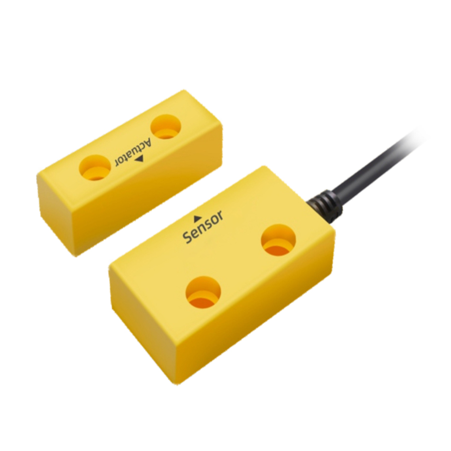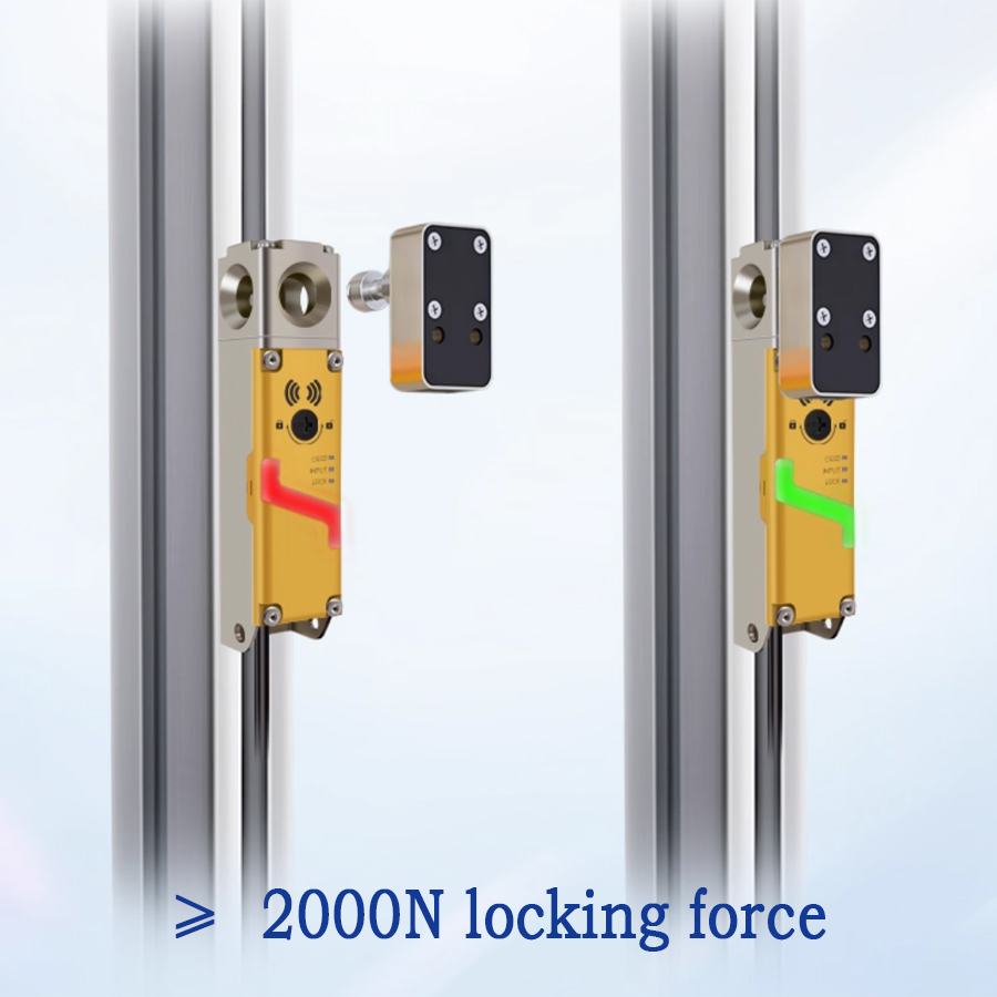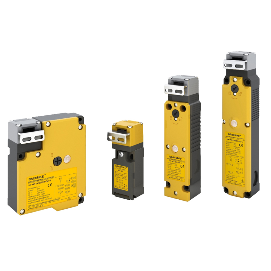
DX-W5 / DX-D2D3 / DX-W3 / DX-W2 industrial machine tool safety door locks

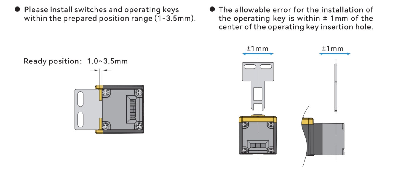
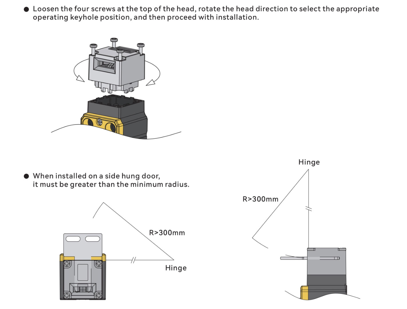
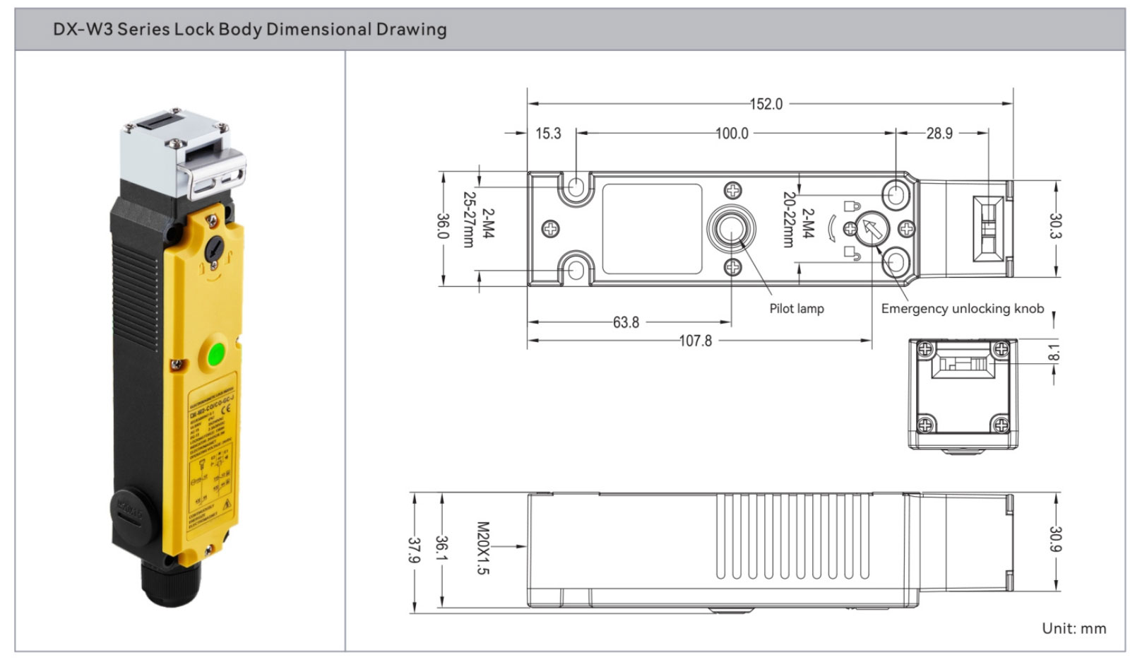
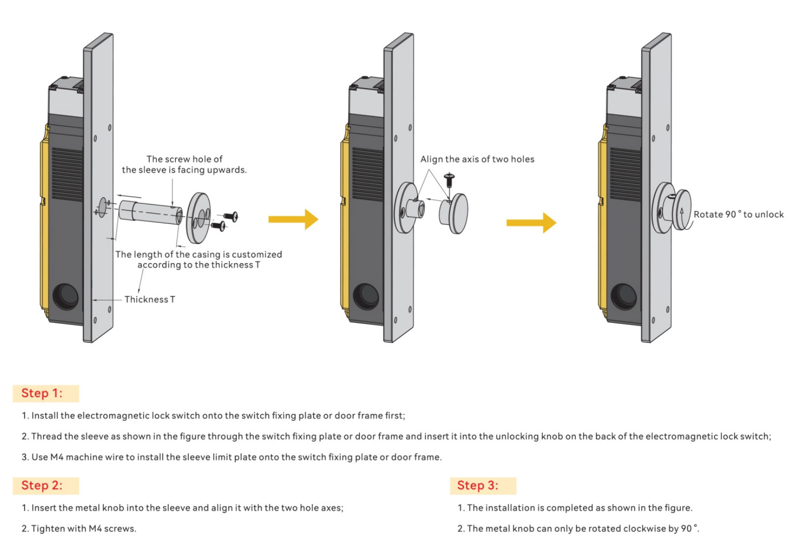
Model-specific mounting illustration: the shown dimensions must not be applied to a different switch or actuator.
| Scenario / Pain Point | Recommended Model | Why This | Typical Applications |
|---|---|---|---|
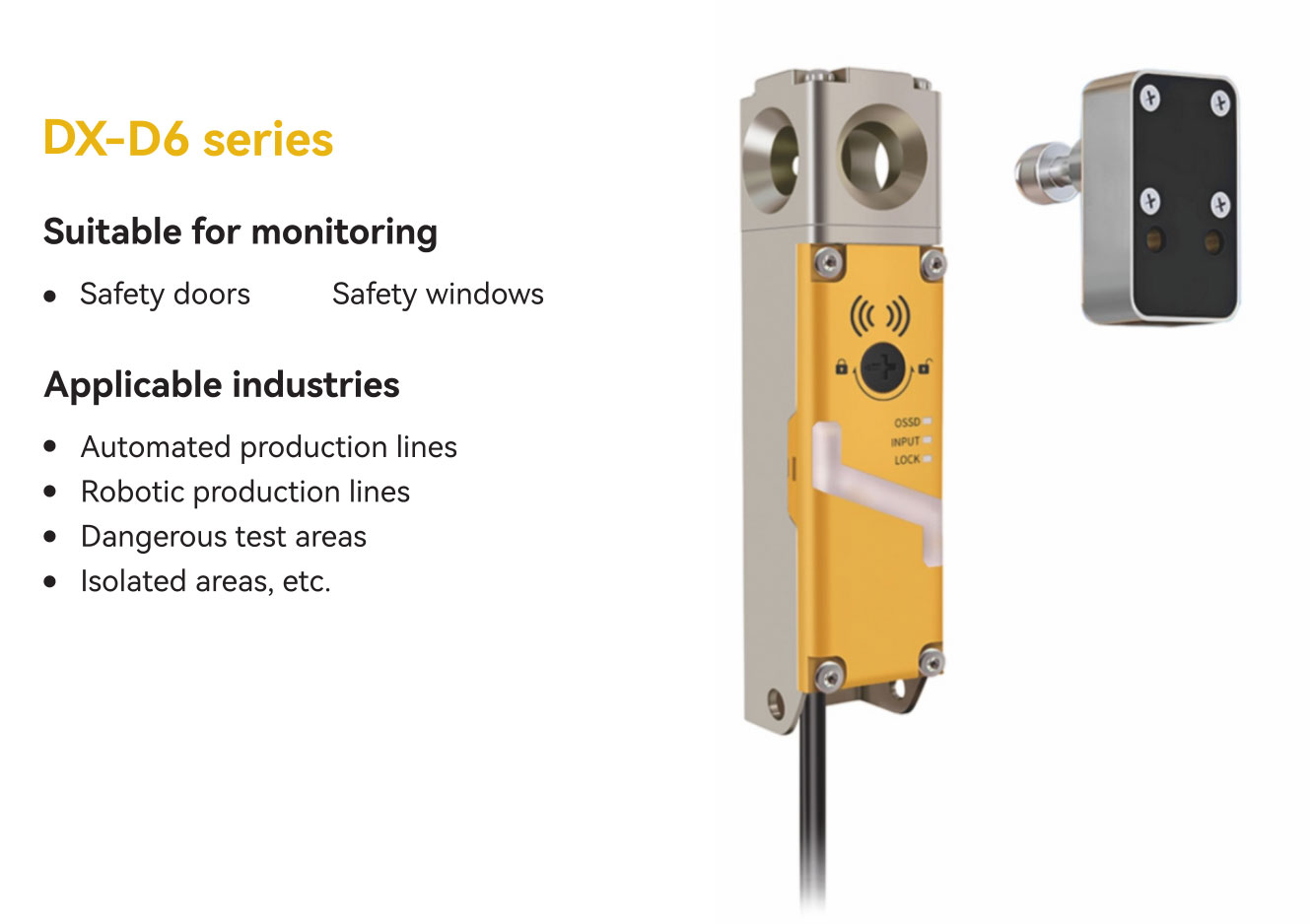
| High risk / inertia — door must stay locked | DX-D6 (locking) | Verify locking/guard monitoring, holding force, release principle, safety interface and connector for the exact ordering code. | Presses / press brakes, robotic cells, welding & cutting units |
| Anti-bypass, wide tolerance, multi-door | DX-R1 (coded non-contact) | Verify coding level, actuator compatibility, operating distances, safety interface and any permitted series arrangement. | Perimeter guarding with many doors; dusty / oily or clean environments; vibration |
| High safety-performance target & large-door misalignment | DX-R1 (coded non-contact) | Check exact-model safety data and mounting limits against the required PL / SIL. The product family name alone does not establish the achieved system level. | Large assembly / packaging lines, big service doors |
| Standard service / guard doors (value) | DX-D2 / DX-D3 position-monitoring interlock | No guard-locking function. First confirm that position monitoring is sufficient for the access and stopping times, then check the exact contacts and controller. Pairing components alone does not establish the achieved PL / SIL. | General machining, common service access |
| Form-factor / mounting compatibility add-ons | DX-W2 / DX-W3 / DX-W5 | Broader shapes & mounting options to match existing holes and space constraints. | Limited space or specified appearance compatibility |
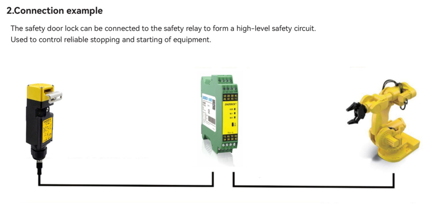
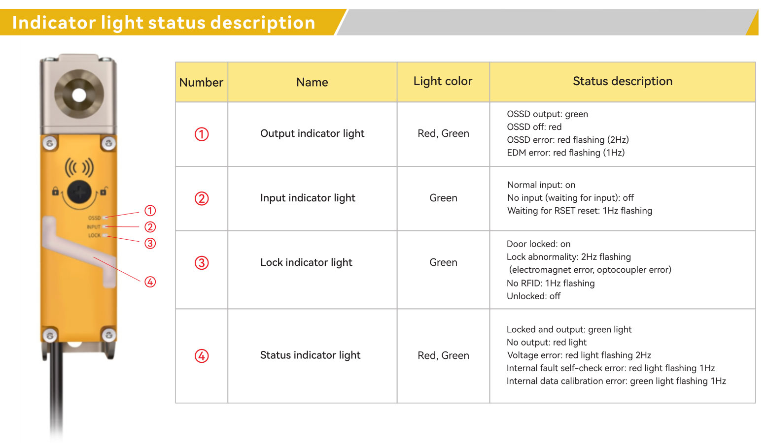
Identify safety contacts versus OSSD outputs and verify the exact controller input, supply, test-pulse compatibility and pinout. An auxiliary status output is not a safety channel.
Confirm the exact coding level and anti-defeat measures. Approved series connections may affect diagnostics and response time; account for fault masking and the whole safety function.
For two-leaf access, use the double-leaf guard door and bolt selection guide to distinguish structural support, position monitoring and guard locking.
Use rigid hinge-style brackets; in high-risk stations prefer locking DX-D6 with official brackets to mitigate sag and vibration.
For rail dust / side-play, check approved brackets and alignment limits. Evaluate non-contact sensing only where suitable; it cannot replace a required guard-locking function.
For brand-replacement checks, compare Euchner and Schmersal interlock functions against DX candidates or review the Pizzato and Fortress replacement requirements. Select compatible safety relay modules for guard-door monitoring only after checking the input and reset requirements.
Selection principles: guard locking and access versus stopping time. For a model-specific example of series-connection limits—not DX specifications—see Schmersal operating instructions.
Document these in your project file: target PL / SIL, locking requirement, coding & anti-bypass strategy, multi-door cascading, door type & bracket, I/O type and connector.
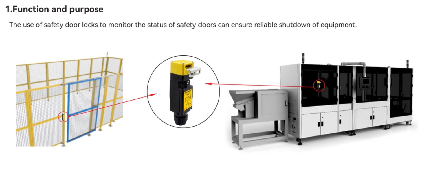
Guard locking for personnel protection is needed where a person could reach a hazard before it has ceased after a stop request. Assess access time, stopping time and other residual hazards. A door-position interlock alone does not hold a guard shut. Select and validate the exact locking function and any required escape or emergency release.
Coding levels and actuator teaching depend on the exact device. Individual coding can reduce the possibility of defeating an interlock with a spare actuator; it does not prevent every form of bypass. Confirm the documented coding level and additional anti-defeat measures for the installation.
Use only a manufacturer-approved series connection for the exact switches and controller. Assess fault masking, accumulated response time, diagnostics, supply limits and the required performance level. Where series connection is unsuitable, use separately monitored safety inputs. Do not improvise a generic output-to-input chain.
Choose mounts that preserve the specified actuator alignment throughout door travel and prevent sag, vibration or door loads from damaging the switch. Use the exact device mounting instructions. A non-contact sensor is not a substitute for guard locking where locking is required.
First establish whether the device uses safety contacts, OSSD outputs or another documented safety interface. Check the exact safety-controller input compatibility, test pulses, terminal assignment and supply. Matching PNP or NPN polarity alone does not establish safety compatibility.
Inspect alignment, door sag, vibration, contamination, cable damage, supply and controller diagnostics using the exact manuals. Isolate hazardous energy before adjustments. Correct the cause and repeat the required functional checks; do not bypass the interlock to suppress trips.