
A rounded arm alone does not establish a safe shared workspace. Include the programmed task, end effector, workpiece, nearby machinery and foreseeable access in the application assessment. For SSM, determine which separation and motion conditions must be monitored safely before choosing the sensing architecture.
What did ISO 10218-2:2025 change for collaborative work?
The 2025 revision incorporated collaborative content from ISO/TS 15066 where appropriate and replaced “cobot” with “collaborative application.” ISO 10218-2:2025 (Edition 2.0) was published on 5 February 2025, alongside its companion ISO 10218-1:2025 for the robots themselves. The most consequential change is structural: the collaborative-safety content that used to live in ISO/TS 15066:2016 — a separate technical specification you had to cross-reference — now sits inside ISO 10218-2 directly.
Application-level assessment prevents a product label from replacing the integration work. The same robot can require different safeguarding with a changed tool, payload, path or task. For the broader integration context, see the ISO 10218:2025 robot-cell briefing.
What are the four collaborative methods, and where does SSM sit?
The familiar four-method list is a legacy explanation. A3's account of the revised standard identifies hand-guiding controls, SSM and PFL as collaborative technologies, and monitored standstill as a safety function also used outside collaboration. Keep that distinction when reading older terminology below.
- Safety-rated monitored stop (legacy term) — now discussed as monitored standstill: absence of motion is monitored with drive power active. Access, fault response and restart conditions require validation.
- Hand Guiding — the operator moves the robot directly through a hand-guiding device with an enabling switch. The robot stays in a safety-monitored stop until that device is actuated.
- Speed and Separation Monitoring (SSM) — robot and operator move concurrently, provided a pre-determined protective separation distance is maintained. This is the “fenceless” method, and the one that depends on a presence-sensing device.
- Power and Force Limiting (PFL) — assess contact and trapping for the complete application, including tool and workpiece. An arm capability does not make all foreseeable contacts safe.
External sensing may also be needed to establish safe access or presence conditions in a monitored-standstill application. PFL assessment includes tools, workpieces, trapping and contact hazards; it is not simply a built-in arm feature. Choose and combine measures for the specific application.
How does Speed and Separation Monitoring actually work?
The safety design can use validated discrete safe fields and speed states or suitably safe dynamic monitoring. Any speed reduction used to justify a smaller separation must itself be safely established before that smaller condition is relied on. Initiate the protective response early enough to maintain the required separation through reaction and stopping. Restart behaviour needs its own assessment; a person stepping away is not universal restart permission.
Do not confuse a scanner's capabilities. Some devices provide safety-rated clear/occupied field outputs while their coordinate or measurement stream is non-safety data. A warning field can support productivity without being credited for risk reduction; if slowing is required for safety, its sensing, interface and speed-monitoring chain must support that claim. The multi-zone field guide covers field selection and transitions.
How is the protective separation distance Sp built up?
Sp is not a single number you read off a datasheet — it is a sum of contributions, and ISO/TS 15066 gives the equation. The minimum protective separation distance is made up of:
- Sh — the operator's change in location, from their approach speed during the robot's reaction and stopping time.
- Sr — the distance the robot travels during its own reaction time, before it begins to stop.
- Ss — the robot's stopping distance once the stop is commanded.
- Uncertainty terms — position-measurement uncertainty for both the operator and the robot.
- C — the intrusion distance from ISO 13855: how far a body part can reach into the sensing field before it is detected.
Use an approach assumption justified by the selected standard and foreseeable scenario. The often-cited legacy 1.6 m/s walking assumption must not be treated as a universal bound for hands, running or every access geometry. If measured human speed or position is used to reduce separation, establish the safety integrity, coverage, latency and uncertainty of that measurement. Apply the relevant reaching and uncertainty additions rather than an arbitrary margin.
Which sensors implement SSM, and what standards govern them?
IEC 61496 provides general and technology-specific ESPE requirements, but does not by itself validate an SSM application. A light curtain provides a defined detection plane; a safety scanner can monitor configured areas. Neither device type automatically reports safety-rated human coordinates or every body part, and occlusions or access above/below the sensing plane must be addressed.
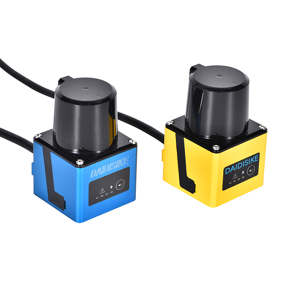
The DLD obstacle-avoidance LiDAR is non-safety sensing equipment and must not be credited as the personnel-protection input of SSM. For a safety scanner, the user-confirmed ST27 capability is Type 3 / PL d / SIL 2; verify its exact manual, interfaces and application limits against the required function. A DQSA light curtain may serve a defined access plane where the exact model and geometry are suitable. Compare plane versus area protection for robot cells before selecting a design.
Where is SSM the right answer — and where is it hype?
SSM earns its complexity when you genuinely need shared space and throughput: an operator who loads parts into the same area a robot works, where a fixed fence would either block access or cripple cycle time. There it is the honest answer, and the scanner-graded slow-down is real engineering value.
A fenceless concept still needs a documented safety boundary. Larger robot motion, payload-dependent braking, blind zones and measurement uncertainty can require more floor space than expected. Compare SSM with an interlocked fenced layout or a monitored-standstill access concept using the same task and risk assessment. Do not shrink a field to recover cycle time without recalculating and validating the safety function.
References & standards cited
- ISO 10218-2:2025 — Robot applications and cells; published 5 Feb 2025; ISO/TS 15066 absorbed.
- ISO 10218-1:2025 — Safety requirements for industrial robots (the robot itself).
- A3 / automate.org — the four collaborative methods explained — including SSM monitored by a safety laser scanner.
- A3 / automate.org — updated ISO 10218 FAQ — on “collaborative application” vs “cobot.”
- ISO/TS 15066:2016 — the protective separation distance Sp equation and the vh = 1.6 m/s human approach default.
- IEC 61496-2 / -3 — light curtains and diffuse-reflection safety laser scanners; ISO 13855 — intrusion distance C and safeguard positioning.