
DK-G Series485 Laser Displacement

DAIDISIKE offers compact M3 / M4 / M5 laser heads and M8 / M12 / M18 through-beam or diffuse-reflection bodies for ordinary part detection, DK-G / LK-F triangulation sensors for displacement, and DAI-JNS10 / DAI-G20 TOF modules for distance feedback. Spot size, surface response, supply and interfaces vary by model. Compare these three tasks below before choosing a mounting size; no model should be assumed immune to sunlight, welding light, black targets or clear plastics.
In heavy dust or oil mist, assess window contamination and maintenance for either laser or LED optics; an IP rating alone does not keep an optical path clear. Where ordinary LED sensing meets the target and range requirements, it remains a valid choice. Compare photoelectric sensing modes or inductive metal-detection switches when those methods fit the task.
Model-name distinction: DK-G is a separate series from the high-precision DDK-G range, formerly called GDK. Do not transfer measuring windows, resolution or output specifications between them; use the full model code when requesting a quotation.
| Body Size | Optical Task / Mode | Model Examples / Selection Boundary | Best-Fit Applications |
|---|---|---|---|
| M3 / M4 / M5 | Compact diffuse-reflection examples | M3: 5–30 / 5–40 mm; M4: 10–50 / 10–70 mm; M5: 10–100 / 10–130 mm by variant | Small fixtures: test the actual part, background and working gap |
| M6 / M8 | DS through-beam examples | 20 m / 30 m respectively in the cited sheet | Separate emitter and receiver; check alignment and actual spot |
| M12 | Through-beam or diffuse-reflection | DS through-beam: 50 m; diffuse: 20–200 / 20–300 mm by variant | Mode selection matters more than matching the thread alone |
| M18 | Through-beam or diffuse-reflection | DS through-beam: 50 m; diffuse: 50–300 / 70–500 mm by variant | Compare one-sided mounting with an opposed pair |
| M30 | Mounting requirement, not a listed model here | Do not infer range from body size; identify an actual laser ordering code | Send the mounting drawing if an M30 envelope is required |
| Displacement (DK-G / LK-F) | Triangulation measurement | Select centre distance and measurement window separately for the exact model | Height, displacement and thickness relative to a defined reference |
| TOF Ranging (DAI-JNS10 / G20) | Distance or threshold feedback | Use the linked model table's distance and reflectance conditions | Ordinary robotic distance feedback or level monitoring, not personnel safeguarding |
A through-beam pair can count suitable containers by their leading edges. Verify the smallest gap, sensor and PLC timing, transparent surfaces and contamination; a narrow beam does not ignore splashes or condensation.
A compact diffuse-reflection sensor can check component presence where the target and mounting gap suit the selected optics. Trial the actual component, solder finish and PCB background before assigning a pass/fail threshold.
An opposed pair across a suitable strip path can provide an ordinary end-of-strip signal. Check oil contamination, strip motion and detection timing. Automatic reloading must remain subject to the machine's separately validated safeguards.
Compare diffuse-reflection and through-beam arrangements for painted parts. Black, white and metallic finishes can return different signal levels; test all intended finishes, approach angles and backgrounds.
A suitable DK-G or LK-F can measure surface position relative to the conveyor reference within its measurement window. Overall parcel volume needs additional dimensions and a validated measurement arrangement; one point does not establish a complete parcel profile or billing accuracy.
DAI-JNS10 or DAI-G20 may provide ordinary distance feedback for docking or cart positioning. Match range, target reflectance, output and timing to the controller. This is not a personnel-protective obstacle-detection function.
DK-G Series485 Laser Displacement
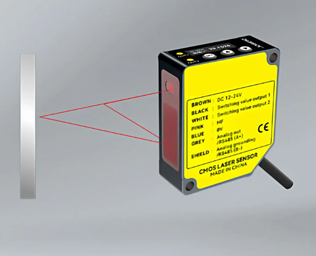
DDK-G (formerly GDK) Laser Displacement Sensor

LK-F Series Laser Displacement

M3M4M5M6 Laser Photoelectric Sensor (one pair)

M3M4M5 Laser Diffuse Reflection (one)

M5M6M8 Laser Diffuse Reflection (one)

M8M12M18 Laser Photoelectric Sensor (one Pair)

M12M18 Laser Diffuse Reflection (one)

TOF Laser Ranging Sensors DAI-JNS10 and DAI-G20
A laser switch uses a laser light source instead of an LED. A specified small spot can help detect edges, holes or small parts, but spot size changes with the optics and working distance. It is not sub-millimeter at every distance: the DS M12/M18 selection sheet lists an approximately 2 mm standard spot and 50 m through-beam range. Check the exact model and target; a laser source does not make every surface detectable or provide immunity to sunlight.
Through-beam uses a separate emitter and receiver and detects interruption of the beam. It can suit long spans when both sides are accessible. Diffuse-reflection uses light returned by the target and suits one-sided mounting, but colour, gloss, angle and background affect operation. Retro-reflective uses a reflector opposite the sensor; choose it where that arrangement fits and verify shiny or transparent targets. No mode is universally best, and dirt on an optical window can affect all of them.
The M-number identifies a metric mounting thread, not a guaranteed sensing distance or minimum target size. Choose the optical mode and actual model first, then check thread, body length, cable exit, spot at the working distance and mounting access. Do not infer a 50 m range or an available product merely from an M30 thread label.
Choose the exact output variant: an ordinary NPN/PNP switching signal, an analog measurement signal, or a documented serial interface. PNP sources current to a sinking PLC input; NPN sinks current from a sourcing input. The DAI-JNS10 table separates PN switching, MI 4–20 mA and 485 Modbus-RTU versions. DK-G and LK-F also have variant-dependent outputs: do not assume a common 0–10 V range, Modbus protocol or wire assignment across families. Check the approved pinout, supply and PLC input specification before wiring. These outputs are not safety OSSD.
Read the exact product's laser-class label and operating instructions. Class 1 concerns accessible emission during normal use; the aversion response to visible light belongs to Class 2, not Class 1. Do not stare into a Class 2 beam or assume every model has the same classification. The required controls depend on exposure, optics, servicing and the application. A laser class does not establish personnel-protective functional safety.
Laser sensing can suit longer optical spans, suitable non-metal targets, or small features that need a specified spot. Inductive sensing detects metal at its documented working gap without an optical window. Select by target, access and environment: transparent, dark or reflective objects need optical trials, while metal size and mounting affect inductive sensing. Neither technology has a universal advantage for every target.
Use the response time and switching or measurement frequency for the exact model and filter setting. For example, the DS M12/M18 selection sheet lists 5 ms response, not a universal 0.5–2 ms. Calculate how long the smallest target and gap remain in the beam, then check sensor response, PLC sampling and actuator timing. A measurement update rate is not automatically the end-to-end response time, and no category-wide line speed is guaranteed.
Selection references: OMRON optical sensing principles and UKHSA laser classification guidance. These explain general boundaries, not certification of a DAIDISIKE model.
Content updated: 2026-09-06. Request the exact model sheet and output pinout before ordering.