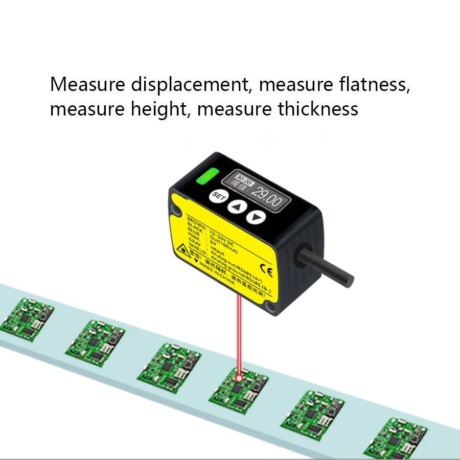
The DAIDISIKE DK-G CMOS laser sensor is a high-precision, non-contact device for industrial tasks like displacement, thickness, and vibration measurement. Laser triangulation measures within a model-specific window around a nominal center distance, not continuously from zero to that distance. Switching, analog and RS485 variants appear in the available source material. Confirm the model and document revision before using the confirmed model-specific figures below for automotive, electronics or semiconductor applications.
Catalogue illustrations are not application test reports. Their general “detection accuracy” labels are not interchangeable with the table's repeatability values; use the confirmed model, distance interval and output rating below.
DK-G is a different family from the DDK-G high-precision series (formerly GDK). Similar housing or a shared catalogue does not make their model codes, ranges or interfaces interchangeable.
The DAIDISIKE DK-G CMOS laser displacement series measures displacement, thickness-related movement, surface profile and vibration within a model-specific window around its nominal standoff. The available center distances are 30, 50, 100, 200 and 400 mm. A reflected spot moves across the receiver as the target moves, and the calibrated sensor converts that position into a measurement.
Select the measurement window, repeatability and output as separate requirements. The confirmed table provides NPN, analog and RS485 order-code rows; analog output is 0–5 V or 4–20 mA, and response is selectable at 1.5, 5 or 10 ms. The IP60 enclosure and −10°C to +40°C operating range require an installation protected from conditions outside those limits. This is an ordinary measurement device, not a safety-rated personnel-protection sensor.
Specifications Table
The table reproduces the confirmed original DK-G ordering and measurement data. A dash marks an unlisted cell, not a claim that a custom version exists or that it is unavailable. DK-G50M is retained exactly as printed; confirm any requested alternative suffix in the quotation instead of substituting one.
Type
Measurement Center Distance
Model (NPN Output)
Model (Analog Output)
Model (RS485 Output)
Measurement Range
Repeatability
Linearity Accuracy
Spot Diameter (Approx.)
Short-range
30 mm
— (not listed)
DK-G30NM
DK-G30N-RS485
±5 mm
10 μm
±0.1% F.S.
Approx. φ50 μm
50 mm
DK-G50N
DK-G50M
DK-G50N-RS485
±15 mm
30 μm
±0.1% F.S.
Approx. φ70 μm
Mid-range
100 mm
DK-G100N
DK-G100NM
DK-G100N-RS485
±35 mm
70 μm
±0.1% F.S.
Approx. φ200 μm
200 mm
DK-G200N
DK-G200NM
DK-G200N-RS485
±80 mm
200 μm
±0.2% F.S.
Approx. φ300 μm
Long-range
400 mm
DK-G400N
DK-G400NM
DK-G400N-RS485
±200 mm
400 μm at 200–400 mm; 80 μm at 400–600 mm (as printed)
±0.2% F.S. at 200–400 mm and 400–600 mm (as printed)
Light source: Red semiconductor laser, 655 nm, maximum output 1 mW; Class 2 as stated in the factory table.
Supply voltage: 12–24 V DC ±10%; the table specifies 10% P-P ripple.
Current consumption: Below 40 mA at 24 V DC; below 60 mA at 12 V DC.
NPN control output: Open-collector output, maximum sink current 50 mA, applied voltage up to 30 V DC; residual voltage below 1.5 V at 50 mA and leakage current below 0.1 mA.
Output action: Light-ON / Dark-ON selectable.
Short-circuit protection: Automatic-recovery type, as listed for the control output.
Analog voltage output: 0–5 V; output impedance 100 Ω. The table identifies +5.2 V as the alarm value.
Analog current output: 4–20 mA; load impedance 300 Ω or less. The table identifies 0 mA as the alarm value.
Response time: 1.5 / 5 / 10 ms, switchable. These are response-time settings, not a published sampling-frequency specification.
External input: NPN non-contact input; active level 0 to +12 V DC; input impedance approximately 10 kΩ.
Operating temperature: −10°C to +40°C; prevent condensation and freezing. Storage: −20°C to +60°C.
Humidity: 35–85% RH in operation and storage.
Ambient light: Incandescent illumination at the receiving surface below 3,000 lx.
Cable: 5-core composite cable, 2 m; conductor cross-section 0.15 mm².
Housing / weight: Aluminium body with acrylic front cover; approximately 35 g without cable and 85 g with cable.
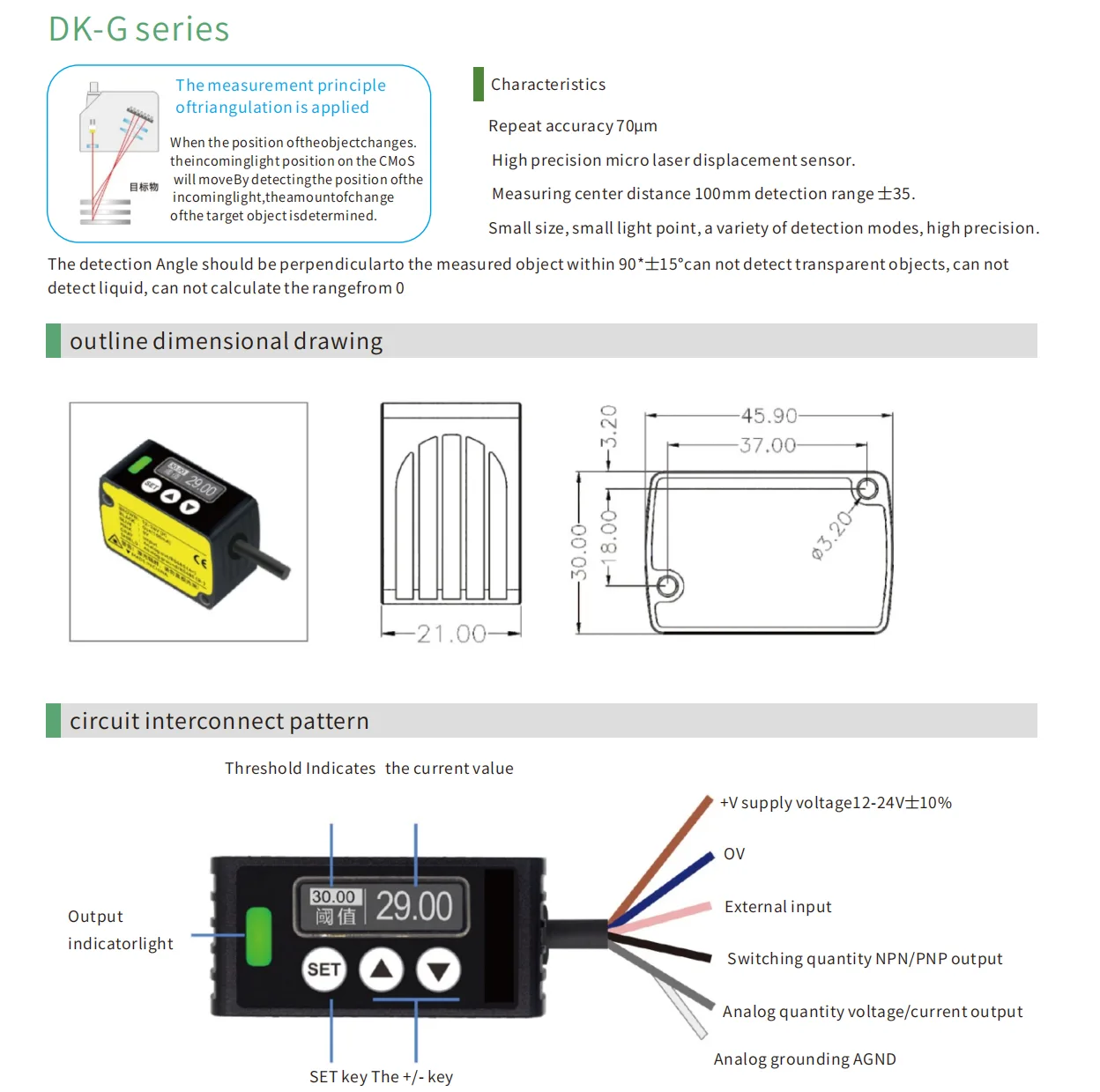
Mounting: M3 screws; the outline drawing shows 45.90 × 30.00 × 21.00 mm and φ3.20 mm mounting holes.
Technical Parameters
Unless otherwise specified, the catalogue's measurement conditions are 24 V DC supply, +20°C ambient temperature, 10 ms response, the measurement center distance and a white-paper target. Those conditions matter when comparing repeatability and linearity. For the 400 mm model, the original table divides repeatability into 400 μm at 200–400 mm and 80 μm at 400–600 mm. This counterintuitive interval split is reproduced as printed under the manufacturer's confirmed source; it is not silently changed to the former webpage's 800 μm.
Optical beam diameter is a length: the 100 mm model lists approximately φ200 μm. A pair of dimensions such as 0.15 × 0.15 mm is not a sampling period. The confirmed DK-G table gives selectable 1.5/5/10 ms response times, not a 1 kHz sampling-frequency guarantee or a sub-1 ms measurement cycle. It also does not establish the former 0.1 μm digital resolution, 300 mW consumption, 100 dB dynamic range, 500 G shock endurance or 15-million-cycle cable life claims. Those unrelated or unsupported values are not specifications for this DK-G series.
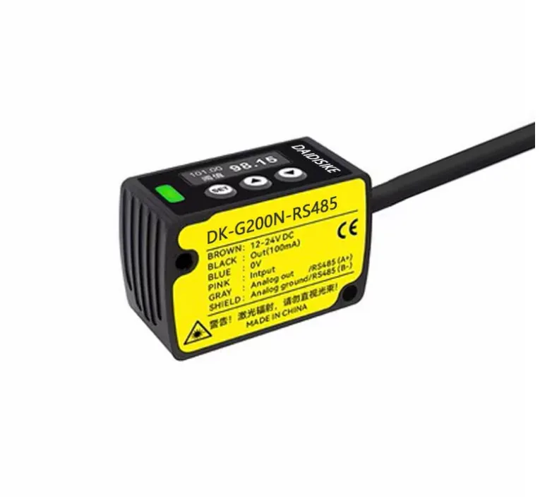
For PLC integration, match the ordered NPN, analog or RS485 variant and its pinout. The table limits NPN control current to 50 mA; the 100 mA text on an illustrative DK-G200N-RS485 product label is not applied to all models. Analog voltage output impedance is 100 Ω, whereas the 4–20 mA output requires a load of 300 Ω or less. Do not confuse output impedance with a recommended voltage-input load. RS485 identifies the interface row here; confirm the matching protocol and register documentation rather than inferring a universal baud rate or command set.
Working Principle
DK-G uses optical triangulation. A 655 nm red laser illuminates the target, and the receiving optics image the reflected spot onto the CMOS receiver. When the target position changes, the received spot position changes. The sensor's calibrated optical relationship converts that position into a distance or displacement value. Displacement is a difference from a calibrated reference distance: zero displacement means the target is at that reference, not infinitely far away.
The former expression d = (f × b) / Δx was not a valid general displacement formula when Δx was defined as a shift from the reference spot. Do not reconstruct a PLC conversion from that expression; use the selected model's documented analog scale or communication data format.
Target reflectance, texture, angle and ambient light can affect the measurement. The original DK-G instructions specify alignment approximately perpendicular to the target within 90° ±15°, exclude transparent objects and liquids, and explain that the window is not measured from zero. Validate the actual material and geometry for displacement, profile, thickness-related movement or vibration measurement. The mounting instructions also address color/material transitions, rotating targets, steps, recessed surfaces and nearby reflective walls. These are installation considerations, not claims of immunity to color, tilt or reflection.
Frequently Asked Questions
How accurate is the DK-G laser displacement sensor?
The current factory table lists repeatability of 10 / 30 / 70 / 200 μm for the 30 / 50 / 100 / 200 mm center-distance models. For the 400 mm model, it prints 400 μm over 200–400 mm and 80 μm over 400–600 mm; those interval-specific figures are reproduced as printed, not replaced by the old webpage's 800 μm. Repeatability, linearity, optical spot size and digital resolution are different quantities. The table does not substantiate the old 0.1 μm digital-resolution claim. Its stated default measurement conditions are 24 V DC, +20°C, 10 ms response, the measurement center and white paper.
What is the measurement range of the DK-G series?
The five center distances and measurement windows are 30 ±5 mm, 50 ±15 mm, 100 ±35 mm, 200 ±80 mm and 400 ±200 mm. These are windows around a standoff distance, not ranges starting at zero. Select a window that contains the full workpiece movement, and check the actual target surface and installation angle.
Does it support NPN, PNP and analog outputs?
The confirmed DK-G ordering table has NPN, analog and RS485 rows. The 30 mm NPN-only cell is blank; the 50 mm analog code is printed DK-G50M, while the other analog codes use NM. This page preserves those entries rather than inventing missing codes. The table specifies 0–5 V or 4–20 mA analog output and a 50 mA NPN control output. An illustrative DK-G200N-RS485 label says 100 mA, but that picture is not used to override the confirmed table. PNP wiring illustrations exist, but a complete PNP ordering matrix is not published here; obtain the exact order code and matching pinout for a PNP requirement.
Is the DK-G laser sensor eye-safe and CE compliant?
The confirmed factory table identifies a 655 nm red Class 2 laser with maximum output 1 mW. Avoid staring into the beam and follow the supplied laser label and installation instructions. Class 2 is a laser-emission classification, not a personnel-protective safety rating. The table's EMC statement and a CE logo are not a standalone certification report; request the exact-model declaration and applicable documentation for a compliance decision.
What protection rating and operating conditions does it have?
The confirmed DK-G table specifies IP60, −10°C to +40°C operation, −20°C to +60°C storage, and 35–85% RH in operation and storage. Prevent condensation and freezing. It also specifies incandescent illumination below 3,000 lx at the receiving surface. The older IP64/IP67 and +45°C claims do not describe this confirmed DK-G table; do not infer washdown suitability or transfer the separate DDK-G family's environmental limits.
Author background: Engineer Cai. Content updated September 6, 2026. The company certificate library is background material; request the exact-model declaration and applicable documentation. Published specifications follow the manufacturer-confirmed DK-G table.