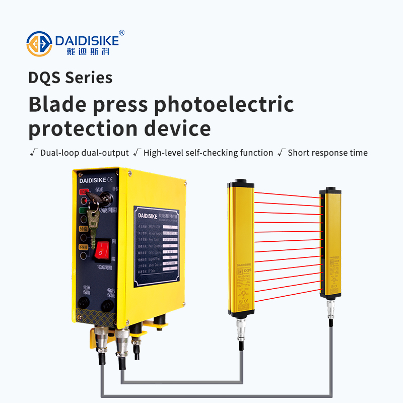
DQS Press Photoelectric Safety Guard Hand Protector

Before selecting the DQS press protector configuration, send the press model and clutch type, opening dimensions, all approach paths, measured stopping time, operating cycle and existing controller/wiring details.
For a bending-machine application, compare the DKE-L3 press brake laser guard and its installation limits. For controller selection, review safety relay input compatibility. These are different decisions, not interchangeable products.
Send your press photos, layout and controller details for a configuration proposal. Include the intended market and documentation requirements; installation and complete-system validation remain machine-specific.
A press guard does not work because it is fast. It works because it is mounted far enough back that the press has finished stopping before a hand travelling at normal speed can reach the tooling. That distance is assessed under the applicable ISO 13855 edition and machine-specific requirements. The expression below illustrates the legacy 2010 vertical, perpendicular upper-limb reach-through method for detection capability d ≤ 40 mm; it is not a complete ISO 13855:2024 design method. See the safety-distance calculation guide for scope and geometry checks:
S = K × T + C
| Term | Meaning | Where the number comes from |
|---|---|---|
| S | Minimum distance from the beam plane to the hazard, in mm | The result — what you are solving for |
| K | Approach speed, mm/s | Legacy method: first calculate at 2000 mm/s; if the result exceeds 500 mm, a 1600 mm/s recalculation may be used, but not below 500 mm. Otherwise the applicable minimum is 100 mm. |
| T | Total stopping performance, in seconds | Press stopping time plus the guard's response time plus the safety relay and contactor response. Measure the press with a stop-time meter — do not use the figure from the machine nameplate, which is what it did when new. |
| C | Intrusion allowance, mm | For this limited legacy reach-through method, d is detection capability, not beam spacing. C = max(0, 8 × (d − 14)) for d ≤ 40 mm. Thus d = 30 mm gives 128 mm; d = 14 mm gives 0. This does not account for reach-over. |
Suppose a defined measurement gives 180 ms for the downstream stop path including its final elements, the selected protector is 10 ms, and its compatible logic contributes 20 ms outside that measured interval. These are illustrative inputs, not a validated DQS/DA31 combination. Count each contribution once: T = 0.180 + 0.010 + 0.020 = 0.21 s. With 30 mm detection capability, C = 8 × (30 − 14) = 128 mm. So:
S = 2000 × 0.21 + 128 = 420 + 128 = 548 mm
The first-stage result is 548 mm. In this legacy method, recalculating at 1600 mm/s gives 464 mm, so the 500 mm minimum for that branch applies. Neither result is an approved installation distance: reach-over, access routes, current-edition and machine-specific rules can require more. Two timing comparisons illustrate why the inputs matter:
Also close the gaps around it. If an operator can reach over, under or around the beam plane, or stand between the beams and the die without being detected, the calculation above is insufficient. Assess supplementary fixed or interlocked guarding, presence detection and restart measures; a second curtain does not automatically close every access route. Remember that a press whose stroke can be re-initiated by clearing the beams (PSDI operation) has additional requirements in most jurisdictions.
First identify the machine and stop capability. Read the OSHA 1910.217 press safeguarding scope for U.S. mechanical power presses and the model-specific press-brake laser guard installation guide for that distinct application.
“Press guarding” covers several different machines, and the right device changes with the tooling and the way the operator works:
| Machine / situation | Device | Why |
|---|---|---|
| Mechanical or hydraulic press, hand feeding at the die | DQS press hand protector | Purpose-built for the die opening, single- or double-sided, ≤ 10 ms response. |
| Press brake — the tool itself must pass through the beams | DKE-L3 laser guard | Evaluate the exact tool-mounted laser system, operating modes and machine interface. A generic light curtain or undocumented muting arrangement is not a substitute. |
| Guarding where a documented Type 4 / PL e rating is demanded by the customer or the audit | DQT4 series | Use where a rating has to be shown on paper rather than inferred from architecture. |
| Candidate safety logic after compatibility review | DA31 or DQSRN safety relay | Verify the exact sensor input and required diagnostics. DQSRN has no manual/automatic reset or EDM; DA31 EDM is not established by current material. Force guidance alone does not validate the complete stop circuit. |
| Removing the hand from the die entirely | Press feeding equipment | Servo roller feeders, decoilers and levellers. The safest press is one nobody reaches into — guarding and automation are usually specified together. |
This practical guide helps manufacturing teams stabilize production with DAIDISIKE® DQS photoelectric safety guards on stamping and forming presses. It covers root-cause diagnosis of false trips, mitigation for oil mist and reflections, parameter tuning and a preventive-maintenance schedule that raises OEE while meeting safety expectations.
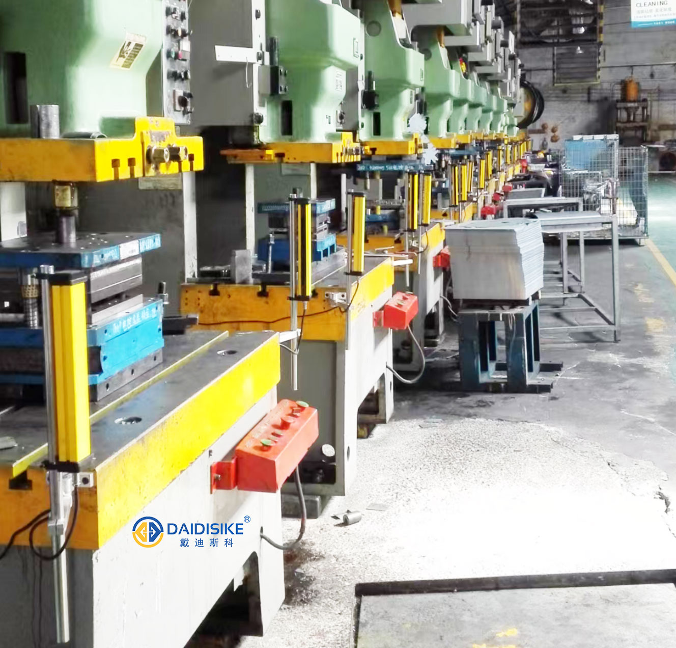
The heading describes a first-pass triage, not a completion or safety guarantee. Isolate hazardous energy before physical adjustments. Follow the applicable lockout and controlled test procedure; no live bypasses.
If the above stabilizes operation, keep the documented safety timing. Do not change response filtering unless the exact controller instructions permit it and the complete safety function is revalidated.
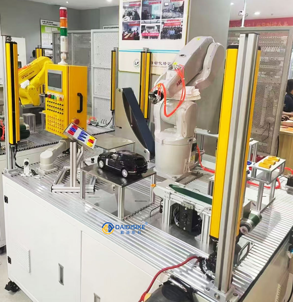

Applies to DAIDISIKE® DQS Punch Press Photoelectric Safety Guard Hand Protector (single-sided and double-sided). Keep safety performance first; do not mask a real hazard.
| Parameter | Purpose | Recommended practice |
|---|---|---|
| Response time / filtering | Suppress micro-chatter from mist or vibration. | Keep the documented default. Only use a controller-supported setting selected by a qualified person; then include it in total stop time, recalculate the ISO 13855 distance and validate the stop function. |
| Sensitivity / gain | Compensate mild soiling without false trips. | Do not assume an adjustable safety gain exists. Use only settings explicitly documented for the exact controller, with the required verification. |
| Alignment indicator | Quantify optical margin. | Interpret the exact model indicator codes. A green indicator or apparent optical margin does not replace a test-piece and complete stop-function check. |
| OSSD integration | Reliable stop command. | Wire according to the supplied controller manual and validated machine safety architecture; avoid sharing returns with inductive loads. |
If you modify timing, update your risk-assessment file and re-run the functional test (Section 6).
Example scheduling prompts only: set intervals and pass criteria from the actual manuals, risk assessment, duty and applicable legal requirements. The table is not a universal DQS maintenance schedule.
| Task | Why | Frequency | Pass / Fail Criteria |
|---|---|---|---|
| Clean lenses (lint-free + neutral cleaner) | Restore optical margin in mist | Each shift (heavy mist) / daily (normal) | Indicator stable green; no haze |
| Bracket & fastener torque check | Prevent drift under vibration | Weekly; after die change | No movement under wiggle test |
| Alignment verification | Confirm beam parallelism | Weekly; after collision | Full-scale alignment markers |
| OSSD stop test (block test) | Prove stop-path integrity | Daily at start-up | Validated stop and restart behaviour within the recorded limits; no instantaneous-stop claim |
| Power-quality check (24 VDC) | Eliminate ripple-induced trips | Monthly | Within the delivered device and supply specifications |
Q1. How do I reduce nuisance trips from oil mist on a photoelectric safety guard?
A. Establish a shift-based lens cleaning routine, use shields or an air knife where the equipment instructions allow them, check alignment and reflections, and verify the 24 VDC supply and cable routing. Re-test the protective function after any adjustment.
Q2. Should I add response filtering to stop false trips?
A. Do not add or change safety-response filtering unless that exact function and value are documented for the supplied controller. First correct contamination, alignment, reflections, grounding and EMC problems. Any permitted timing change must be made by a qualified person, included in the total stopping time, followed by a new ISO 13855 distance calculation and validated stop tests.
Q3. Where should the shielded cable drain be bonded?
A. Follow the controller and machine electrical instructions. Where single-point shield bonding is specified, terminate it at the designated controller or cabinet point, keep sensor cables separated from motor leads, and verify protective bonding and EMC performance during commissioning.
For the current positioning standard see ISO 13855:2024. U.S. mechanical-power-press rules, including the full-revolution-clutch restriction, are in OSHA 1910.217; hydraulic presses and press brakes have separate scope considerations.