DA31 Safety Relay Product Manual
Seven-page DA31 product manual. This is not the separate two-page foldout.

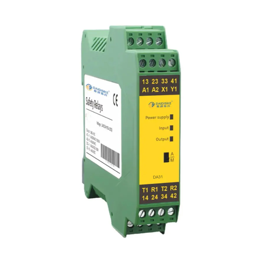

The DA31 series safety relay by DAIDISIKE is a compact, reliable device for industrial safety, monitoring emergency stops, safety light curtain signals, safety door interlocks and two-hand controls. Used in industries like CNC, robotics, and hydraulics, it is rated to EN ISO 13849-1 Cat. 4 / PL e and IEC 62061 SIL 3 per the manufacturer's specification. Its ultra-slim 22.6 mm housing, configurable dual-channel input and separate transistor status output help streamline installation and reduce wiring complexity.
Request the datasheet >>| Item | Specification Description |
|---|---|
| Power Supply Voltage | 24V DC, Voltage Tolerance +10%/-20% |
| Power Dissipation | 2.9W |
| Relay Safety Output | 3 Normally Open forcibly guided safety contacts + 1 Normally Closed auxiliary signalling contact; verify terminal numbering on the supplied unit |
| Wiring revision | Use the delivered label and matching wiring diagram: supplied illustrations differ in power/reset terminal names and show 41/42 or 43/44 for the auxiliary contact. Do not interchange these terminal maps. |
| Transistor Signal Output | <500mA, 24V DC |
| Safety Input | Dual-channel input. Factory wiring examples show PNP light curtains and contact-based devices; confirm NPN and OSSD test-pulse compatibility against the exact supplied revision's instructions. |
| Input Modes (DIP-switch selectable) | Multifunction DIP configuration for applications including emergency stop, safety light curtain, guard-door switch and two-hand control; use the mode table for the supplied revision. |
| Relay Contact Capacity | AC-1: 6A/250VAC / 1500VA · AC-15: 4A/240VAC · DC-1: 6A/24VDC / 150W · DC-13: 4A/24VDC |
| Maximum Switching Capacity | 12A (distributed across all safety output contacts) |
| Contact Resistance | <100 mΩ |
| Minimum Load | 10mA / 5V |
| Contact Material | AgSnO2 + 0.2 µm Au |
| External Output Fuse | 5A gL/gG |
| Release Response Time | <30ms (from input to output) |
| Electrical Life | 80,000 operations |
| End-of-line Detection Resistance (safety edge / safety mat inputs) | 1 kΩ – 10 kΩ |
| Rated Impulse Withstand Voltage | 2.5 kV |
| Pollution Degree | 2 |
| Safety Level | EN ISO 13849-1 Category 4 / PL e; IEC 62061 SIL 3 (manufacturer brochure/label; obtain exact-model supporting documents) |
| Operating Temperature | -25°C to +85°C |
| Storage Temperature | -40°C to +105°C |
| Operating Humidity | 35% – 85% RH (no icing or condensation) |
| Installation Method | Standard 35 mm DIN rail / spring clip |
| Dimensions | 112mm × 99.5mm × 22.6mm |
| Weight | 172 g |
| Protection Grade | Housing IP30, terminals IP20 — install inside an IP54 cabinet or enclosure |
| Housing Material | Flame-retardant PA66 |
| Certification | Contact factory for certification documents |
The technical parameters of the DA31 series focus on safety performance and electrical characteristics. The power supply is 24V DC, with a tolerance range of +10% to -20%, and power consumption of 2.9W. The input stage is a dual-channel safety input with multifunction DIP configuration for applications including emergency stop, safety light curtain, safety door interlock and two-hand control. Factory diagrams illustrate PNP and contact-based inputs; verify any NPN or pulsed OSSD connection against the instructions for the supplied revision. The output provides 3 forcibly guided normally open safety contacts and 1 normally closed auxiliary contact, with terminal numbers verified on the delivered unit. Contacts are rated AC-1 6A/250VAC with a maximum total current of 12A, plus a separate transistor signalling output below 500mA at 24V DC. The response time is less than 30ms, ensuring quick release. The operating temperature range is -25°C to +85°C and storage is rated -40°C to +105°C. The module is rated to EN ISO 13849-1 Cat.4/PLe and IEC 62061 SIL 3 according to the manufacturer's specification. The housing is flame-retardant PA66 with IP30 protection (IP20 at the terminals), so the module is designed to be mounted inside an IP54 cabinet or enclosure on a standard 35 mm DIN rail. Request the exact model's safety documentation; the factory brochure and company certificates do not by themselves validate a complete machine safety function.
The core working principle of the DA31 series safety relay is based on a dual-channel safety input architecture: two independent input channels are monitored, so the safety function does not depend on a single channel. When the connected safety device is actuated, the module drops out and the forcibly guided contacts open to remove power from the hazardous machine function.
The specific workflow is as follows:
Note: the DA31 carries a reset selector — the factory wiring diagram shows the SRC/SR terminals configured either for manual reset or, when linked, for automatic reset on that illustrated revision. Input open-circuit detection and inter-channel checking are described in the terminal table; their coverage and operating conditions require the matching manual. EDM feedback is not established by these diagrams. Reset must not initiate hazardous motion, and terminal maps from different illustrations must not be combined.
A safety relay like the DA31 is a hardwired, fixed-function device that monitors emergency stops, safety light curtains or door switches through dual-channel redundant inputs and cuts output in under 30 ms. A safety PLC is programmable and scales to many zones and complex logic. For a single machine or a few safety functions, the DA31 is faster to wire and lower cost.
The manufacturer brochure and product label reference EN ISO 13849-1 Category 4 / Performance Level e and IEC 62061 SIL 3. This is a manufacturer specification, not proof that a complete machine achieves those levels. Dual-channel monitoring and forcibly guided contacts support fault detection in an appropriately designed circuit; obtain exact-model supporting documents and validate the complete safety function.
Multifunction DIP configuration for applications including emergency stop, safety light curtain, guard-door switch and two-hand control; use the mode table for the supplied revision. Dual-channel input. Factory wiring examples show PNP light curtains and contact-based devices; confirm NPN and OSSD test-pulse compatibility against the exact supplied revision's instructions. The application examples are not a claim of exactly four DIP settings or automatic interchangeability with another manufacturer's sensor.
The DA31 measures 112 × 99.5 × 22.6 mm and mounts on a standard 35 mm DIN rail. Its 22.6 mm housing width is confirmed by the factory dimension drawing. Use the delivered label and matching wiring diagram: supplied illustrations differ in power/reset terminal names and show 41/42 or 43/44 for the auxiliary contact. Do not interchange these terminal maps. Isolate power before wiring, and validate the input, reset and final switching-device circuit before operation.
The DA31 provides 3 forcibly guided normally open safety contacts plus 1 normally closed auxiliary contact for status signalling. The factory table lists AC-1 6 A/250 VAC, AC-15 4 A/240 VAC, DC-1 6 A/24 VDC and DC-13 4 A/24 VDC. DC-1 and DC-13 are different load categories, not conflicting versions of one rating. The maximum 12 A is distributed across all safety output contacts, not 12 A per contact. A separate transistor signalling output is rated below 500 mA at 24 VDC and must not be treated as a safety output. Select the contact rating for the actual load category.
Seven-page DA31 product manual. This is not the separate two-page foldout.
Confirm the document and CAD file match your exact ordered version before installation or mechanical design. Contact us if your model is not listed.
Engineering contact: Engineer Cai, Senior Application Engineer. See certificates.