
Safety Relay vs Safety PLC — Selection Guide for Machine Safety Designers
Chosen a relay already? The terminal-level wiring — OSSD channel pairs, the EDM feedback loop through the contactor auxiliaries, reset mode selection and the commissioning trip test — is covered in light curtain wiring diagrams and terminal maps.
Choose a relay or safety PLC from the required cause-and-effect logic, independent restart zones, diagnostics, response time and future changes—not a fixed count of safeguards. Both device classes can support high-integrity functions when correctly selected and validated. The safety relay selection overview covers the relay-side evidence to obtain; compare it against an equally documented programmable architecture.
The question of relay vs PLC for safety logic shows up on every new machine design. The answers in the field range from "always PLC, because you can change it later" to "always relays, because you don't have to certify your code." Neither extreme is right. The honest answer is architectural: the right safety logic element falls out of the safety functions you actually have, their relationship to each other and the machine's life cycle. This guide walks through both options the way an experienced control engineer would think about them, and ends with a clear decision matrix.
1. What a safety relay actually is
A safety relay is an electromechanical or electronic device for its documented safety functions. Depending on the model, it evaluates contact inputs or compatible ESPE outputs and commands the required stop through suitable final switching devices. Input architecture, fault response and restart behaviour are model- and mode-specific; a generic relay label does not establish these capabilities.
Compare these architectural features against the exact device manual:
- Input architecture — verify permitted single-/dual-channel arrangements, discrepancy limits and the documented response to each required fault.
- OSSD test-pulse compatibility — compare sensor pulse width and interval with the exact controller input requirements.
- Fault detection — obtain the supported input cross-circuit and internal diagnostic functions; do not infer them from channel count.
- EDM (External Device Monitoring) — where supported, the controller monitors documented feedback from the final switching devices. Check the required diagnostics in the complete safety-function design; EDM alone does not determine Category or Performance Level.
- Reset logic — manual or automatic reset according to the risk assessment and the documented circuit, including protection against unexpected restart.
- Output stage — distinguish safety contacts or semiconductor safety outputs from auxiliary signalling. Match coil loads to utilization-category ratings, current limits and prescribed suppression.
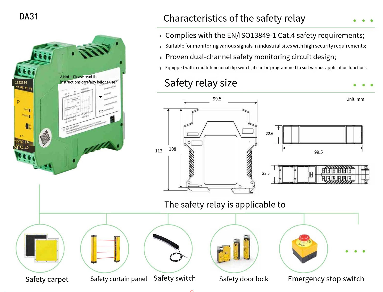
The DAIDISIKE DA31 uses a 22.6 mm DIN-rail housing with a dual-channel input, multifunction DIP configuration, three normally open safety contacts (13/14, 23/24 and 33/34) and one normally closed auxiliary contact. The brochure lists E-stop, light-curtain, door-interlock and two-hand applications; these are application examples, not an exact count of selector positions. Factory material shows SRC/SR reset configuration and input open-circuit detection with channel cross-checking. Match the mode table and all terminal numbers to the delivered version: source drawings use different terminal labels, including 41/42 and 43/44 for the auxiliary contact. The documented cross-checking does not establish full diagnostic coverage, EDM or monitored-reset equivalence. A delayed-output variant is not established by this DA31 documentation.
Route both documented safety outputs to compatible safety inputs. Compare supply, test-pulse handling, response time and required fault detection in both manuals. Obtain the exact controller terminal drawing; a different relay's reset or feedback circuit is not evidence of DA31 compatibility.
2. What a safety PLC actually is
A safety PLC is a programmable safety controller with documented safety hardware, a supported development environment and safety-function capabilities. Check its exact hardware/software revision, permitted function blocks, safety data and configuration limits. Not every controller or configuration has the same integrity rating, I/O diagnostics or response time; the application program and complete function still require validation.
The architectural advantages over a safety relay are:
- Multiple functions — suitable models can evaluate several functions or independent zones when their I/O, approved blocks, response budget and configuration limits satisfy the design.
- Shared safety state — a documented safety program can coordinate zones and operating modes. Define the safe-state dependencies and validate every transition; ordinary status bits are not safety authority.
- Specialized sequencing — muting requires supported safety functions and a validated material-flow design. PSDI is a separate, machine-specific operating function; a generic PLC or muting block does not authorize presence-sensing initiation.
- Diagnostic visibility — documented status data can be reported over a non-safety channel to support fault finding. Check which states are available; no fixed downtime improvement is established.
- Changeable logic — when a recipe change requires a different safety function configuration (typical on multi-product packaging lines, semiconductor cluster tools and battery formation rooms), the program may be revised within the hardware limits. Review access control, configuration management and revalidation; changed logic is not automatically safe.
The disadvantages are also real:
- Hardware and software cost — compare the quoted controller, I/O and licence cost for the same safety functions; there is no fixed price multiplier against a DA31 relay.
- Higher commissioning effort — programming a safety controller is a regulated activity; the program needs to be reviewed and validated against the safety functions in the risk assessment, and the validation evidence kept with the technical file.
- Response-time budget — compare documented worst-case input-to-output time, configured I/O and any safety-network delays with the candidate relay; the device class alone does not establish which is faster.
- Vendor lock-in for software — both software and wiring depend on the selected hardware. A different controller requires an engineering review; relay terminal drawings are not automatically portable either.
3. The eight-question decision matrix
Use these eight questions to document design constraints, not as a scored vote. A single mandatory function can exclude an otherwise attractive relay or PLC. Record the requirement, evidence from the exact device manual, proposed implementation and validation method before selecting either architecture.
| # | Question | If yes |
|---|---|---|
| 1 | Does the required architecture exceed the candidate relay’s documented inputs, outputs or logic? | PLC |
| 2 | Do any two safety functions need to share state (zone interlock, conditional override)? | PLC |
| 3 | Is muting or PSDI required, with timed input sequencing? | Documented specialized function; PSDI requires separate machine-specific approval |
| 4 | Does the safety configuration change between recipes or product variants on the same machine? | PLC |
| 5 | Is per-zone or per-function diagnostic reporting to the line PLC or HMI required? | PLC (or relays + dedicated reporting wiring) |
| 6 | Will the machine evolve over its life — extra stations added, safeguarding revised? | PLC |
| 7 | Is the cycle time aggressive enough that 30 ms of extra response time would force a wider safety distance? | Compare the actual validated response budget |
| 8 | Does the controls engineering team lack a certified-safety-programming workflow today? | Arrange competent design and validation support |
Response time and engineering capability deserve explicit checks. Compare documented worst-case stopping-chain times for the actual designs; do not assume relays are always faster. Lack of a safety-programming workflow does not justify using relays that cannot implement the required function. Arrange competent design and validation support for whichever architecture meets the requirements.
4. Cost reality — the numbers people don't quote
Direct unit-price comparison is only half the picture. A safety PLC's installed cost includes the controller, the IO modules for the channel count required, the programming software licence, the safety programming labour, the validation labour and the documentation. A safety relay's installed cost also includes final switching devices, panel work, wiring and validation. The checklist below identifies items to quote for a single-zone cell with an emergency stop, a safety light curtain and a safety door switch. It is not a priced bill of materials or a fixed labour estimate; both routes must meet the same validated requirements.
| Line item | Safety relay route | Safety PLC route |
|---|---|---|
| Safety logic device | Safety relays with documented input and diagnostic support; quantity follows the validated architecture | 1× small safety PLC + DI/DO modules |
| Safety output contactors | Final switching devices and feedback circuit matched to the selected controller's documented support | Final switching and feedback devices required by the validated architecture |
| Programming licence | Not required | Vendor-specific tools; confirm licence terms in the quote |
| Engineering labour | Quote circuit design, wiring drawing and panel build for the chosen architecture | Quote programming, I/O configuration, panel build and validation preparation |
| Commissioning labour | Loop, required feedback and reset tests; duration depends on the validated circuit | Input/output, program function, feedback and reset tests; duration follows the validation plan |
| Documentation | Schematic, required feedback diagnostics and reset behaviour records | Schematic, safety program listing, validation record, version log |
| Installed-cost comparison | Supplier quotations plus wiring, commissioning, documentation and anticipated changes | Supplier quotations plus software, programming, commissioning, documentation and anticipated changes |
Adding functions can change the comparison: a relay architecture may require more devices and wiring, while a PLC architecture may require additional I/O, software and validation. Evaluate those changes using the actual design instead of a fixed function-count break-even rule. Include the DA31 where its documented input modes and output ratings match the application, and compare the full installed scope with a suitable programmable controller.
5. Architectural ceiling of a single safety relay
When evaluating a single DA31 safety relay, check:
- The selected documented input mode for the ESPE, E-stop or door function. A listed two-hand mode does not establish the required type, timing or anti-tie-down behaviour.
- The three NO safety contacts and required load rating for the final switching devices.
- The manual or automatic reset configuration in the factory drawing.
- The NC auxiliary and transistor signalling outputs for ordinary status reporting.
- Any required EDM or specific diagnostic coverage: the DA31 terminal table describes input open-circuit detection and inter-channel checking, but the exact manual must establish coverage; EDM is not established by those drawings.
A machine with several safeguards may use separate safety relays or a programmable safety controller. Select a documented architecture that causes every required stop request to remove permission for hazardous motion. Verify combined diagnostics and reset behaviour instead of assuming that parallel relay outputs form a safe common stop circuit. Typical functions to account for include:
- Relay 1: Emergency stop (red mushroom on the panel front).
- Relay 2: Safety light curtain at the load opening.
- Relay 3: Safety door switch on the maintenance access panel.
- A validated common stop circuit and restart interlock that responds to each safeguard; use the controller manufacturers' approved wiring.
Shared conditions, independent restart zones or specialized muting logic may favour a controller even at a low function count. Conversely, additional fixed functions do not automatically invalidate a documented relay architecture. Evaluate the cause-and-effect matrix, diagnostics and validation effort; do not treat a generic rule about four functions as a design limit.
Define the required stopping and restart behaviour, then verify input diagnostics, three safety N.O. output contacts, load ratings and final switching devices in the applicable design. DA31's auxiliary N.C. output is signalling, not a fourth safety output.
Required monitored reset or EDM needs explicit manufacturer support. A catalogue illustration cannot establish fault coverage or approve the complete safety function.
6. Response-time budget and ISO 13855
Choose the applicable safeguard-positioning method from ISO 13855:2024, including approach geometry and detection capability; the familiar S = K × T + C expression is not a universal method for every installation. T is the applicable complete system response time. T includes everything from a finger entering the safety field to the hazardous motion coming to rest, so every element in the safety chain contributes:
| Element | Response-time input | Notes |
|---|---|---|
| Safety light curtain | Use the exact model's documented response time | Verify its documented type and configuration separately; a product-family name does not establish a Type 4 rating. |
| ST27 Type 3 safety laser scanner | Published 100 ms; confirm the selected configuration | Use the exact model's configured safety response. DLD perception LiDAR is not a safety-scanner substitute. |
| DA31 safety relay | Published release response <30 ms | Confirm the documented operating conditions and which delays are included; do not infer unlisted cross-fault diagnostics. |
| Local safety PLC | Use the validated worst-case controller response | Include input processing, safety program execution and output update under the selected configuration. |
| Networked safety PLC (over a safety bus) | Include the configured safety-communication response | Adds the worst-case bus message latency at the configured update rate. |
| Safety contactor opening | Use documented and validated release time | Account for the selected coil, load and suppression circuit. |
| Mechanical stopping time | Measure under the worst relevant operating conditions | Include the machine's actual load, speed and stopping mechanism; do not use a generic value. |
A longer safety-logic response can increase the required separation distance even when the mechanical stop dominates the total time. Do not dismiss a delay as negligible from the machine's production rate alone. Use the applicable ISO 13855 method, the measured stopping performance and the documented worst-case response of each selected component, avoiding double-counting delays already included in an end-to-end measurement. Revalidate the distance when the controller, program, network or final switching devices change.
7. Wiring topology comparison
The following are functional examples, not terminal drawings or approved circuits:
Safety relay topology
ESPE OSSD pair → compatible safety relay input → documented relay logic → safety output contacts → final switching devices → hazardous motion. Where feedback monitoring is required, follow the exact controller and contactor manuals. For the DA31, use the factory terminal map and reset configuration; its current documentation does not establish an EDM input or cross-fault-detection function.
Commissioning follows a documented validation plan covering input faults, output response, required feedback diagnostics, stopping performance and reset behaviour. Carry out prescribed fault tests under the equipment manufacturers' instructions and retain the results with the validated circuit drawing.
Safety PLC topology
In one documented contactor-based example: ESPE OSSD pair → compatible safety PLC DI module input pair → safety program logic → safety PLC DO module output pair → safety contactors K1 and K2 in series → motor power. K1 and K2 mirror NC auxiliary contacts in series → safety PLC DI module EDM input. Reset button → safety PLC DI module reset input; program implements the required reset logic. Use the exact controller and contactor manuals; this example does not require two contactors for every possible stopping architecture.
The wiring drawing is similar; the safety program is the new artefact. Commissioning adds the safety-function validation step against the risk assessment, which has to be done once per function and recorded.
8. When the wrong choice shows up later
The cost of getting this wrong is usually a year or two later, when the machine is in production and the line is asked to do something it was not originally designed for. Two typical patterns:
- Illustrative expansion question: a second safety door is required but the panel is full. Compare additional documented relay hardware with a controller redesign, including physical space, diagnostics and an application-specific shutdown plan.
- Illustrative response-time question: the proposed controller delay does not fit the available separation distance. Recalculate the complete documented stop chain and assess a different controller, safeguard arrangement or mechanical layout; use measured values, not generic example distances.
The way to avoid both is to walk the eight-question matrix honestly at the design stage and to size the response-time budget against ISO 13855 with the actual planned safety architecture, not the first one that came to mind.
9. The DAIDISIKE DA31 safety relay family — neutral product reference
Since this is the DAIDISIKE site, a short reference to our own safety relay line so it sits in context. The DA31 documentation lists input modes for emergency stops, safety light curtain OSSD signals, safety door interlocks and a two-hand mode. The latter requires separate evidence for the required control type, timing and anti-tie-down behaviour; its label alone is insufficient. For any specific curtain, door switch or ST27 safety scanner, check the sensor's electrical output, test pulses, the controller input mode and the complete circuit before confirming compatibility.
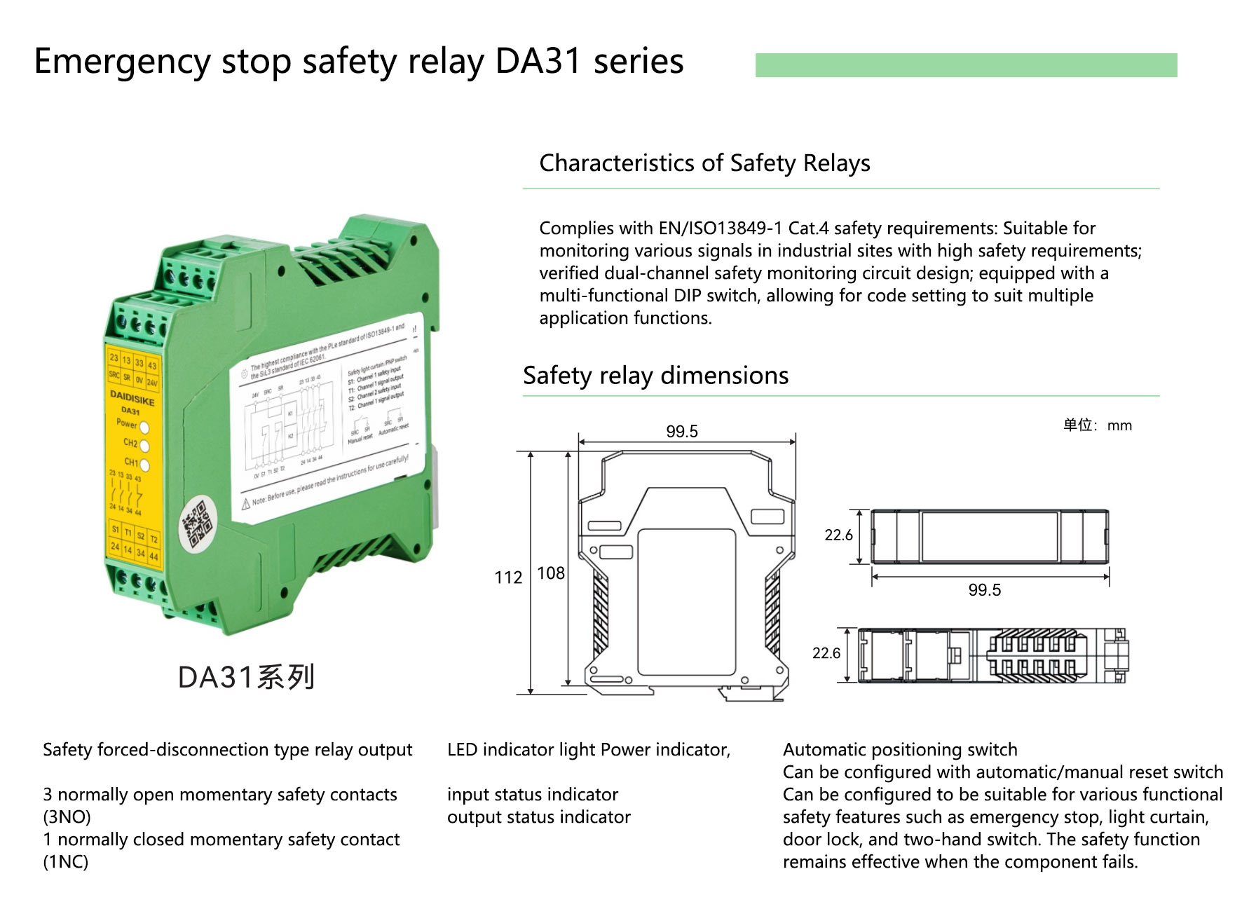
The DA31 product page lists dual-channel PNP or NPN inputs, three forcibly guided NO safety contacts, one NC auxiliary contact and a 24 V DC supply. Published contact ratings include AC-1 6 A / 250 V AC and AC-15 4 A / 240 V AC; select the rating for the actual load category. The factory drawing supports manual or automatic reset configuration. EDM and delayed-output functionality require separate confirmation and must not be assumed from this selection guide.
To talk through a specific safety architecture and whether the relay or PLC route fits, open a conversation at our contact page or look at the DA31 safety relay module, DAIDISIKE safety light curtain family and ST27 safety laser scanner and industrial LiDAR range to compare the components and their documented roles. Only the certified safety-scanner models belong in the personnel-protection stop function; the industrial perception models have a separate role.
10. Frequently asked questions
What is the difference between a safety relay and a safety PLC?
A safety relay is a fixed-function safety controller that takes a small number of safety inputs — typically an emergency stop, a safety light curtain pair, a safety door switch — and drives one or two pairs of safety outputs that cut power to the hazardous motion. Its logic is hardwired. A safety PLC is a programmable safety controller: the same inputs and outputs are available, but the logic between them is written in a safety-certified programming environment (typically a restricted subset of IEC 61131-3) and can implement several independent safety functions on the same hardware. The architectural difference is configurability, not safety level — both can reach PL e under ISO 13849-1 and SIL 3 under IEC 62061 when correctly applied.
When is a safety relay enough and when do I need a safety PLC?
Use a fixed-function relay when its documented modes, inputs, outputs and restart diagnostics implement the complete required function. Consider a safety PLC when shared zone state, configurable logic, distributed I/O or diagnostics justify it. There is no universal three- or four-function threshold: compare both validated architectures and their lifetime engineering cost.
Can a single safety relay handle a light curtain and an emergency stop together?
Only if the exact safety controller is documented to monitor both functions with the required independent inputs and logic. Two channels of one dual-channel input are not two independent safety functions. Alternatively, use a documented multi-relay architecture with a validated common stop circuit: either safeguard demanding a stop must remove permission for hazardous motion. Do not wire outputs in parallel at a contactor coil and assume that either relay opening will stop the machine. Confirm input compatibility, fault detection, reset behaviour and the complete output circuit using the manufacturers' approved diagrams.
What is EDM and why does my safety relay need it?
EDM stands for External Device Monitoring. In a controller documented to support it, feedback from the final switching devices is checked so a detected failure can prevent restart. The appropriate mirror-contact feedback circuit and its timing must follow the controller and contactor manuals. EDM is one part of the safety-function design; adding it alone does not establish Category 4 or PL e. The current DA31 factory documentation does not state EDM support, so confirm a suitable documented architecture if your application requires it.
What is the difference between manual and automatic reset?
Manual reset requires a deliberate reset action after the safeguard clears; automatic reset permits the safety outputs to re-energise when the documented input conditions are satisfied. Select the mode through the machine risk assessment, including any possibility of a person remaining in the hazardous area. Resetting a safeguard must not by itself initiate hazardous motion. Use the exact model's reset wiring: the DA31 factory drawing shows SRC/SR configuration for manual or automatic reset, but this does not confirm EDM functionality or justify a generic jumper-to-24-V instruction.
How many safety relays can I daisy chain before a safety PLC makes more sense?
There is no universal maximum count or cost break-even. Check permitted interconnections, cumulative response time, diagnostic coverage, panel capacity and the ability to trace and validate each function. A configurable controller can simplify shared logic, but a relay system is acceptable only within its documented and validated architecture.
Does a safety relay or safety PLC affect the response time of a safety light curtain?
The controller does not change the sensor's own response time, but it adds delay to the complete stopping chain. Use the sensor's configured response time, the safety logic's documented worst-case input-to-output time, final switching-device response and measured mechanical stopping performance in the applicable ISO 13855 calculation. Networked controllers also require the documented safety-network timing. The required distance depends on the complete installation, so do not select a controller using an assumed generic response time or an unsupported example distance.
Can a DAIDISIKE DA31 safety relay be used with any brand of safety light curtain?
The DA31 factory wiring examples show dual-channel PNP light-curtain inputs, and the brochure describes multifunction DIP configuration. Check NPN support and OSSD test-pulse compatibility in the manual for the delivered version, together with the exact sensor's electrical characteristics, input settings and approved wiring. DA31 provides three normally open safety contacts and one normally closed auxiliary contact; its current factory documentation does not establish EDM support. For a scanner such as the Type 3, SIL 2, PL d ST27, verify the complete sensor, safety logic and final switching-device circuit before selecting the combination. Neither a shared brand nor the OSSD label alone confirms compatibility. DLD-series perception LiDARs must not replace the safety scanner.
How much more expensive is a safety PLC than a safety relay?
There is no verified universal price multiplier. Compare quotations for the same safety functions and include controllers, I/O, final switching devices, software licences, panel space, wiring, programming, validation and future changes. A fixed-function relay may suit a simple circuit; a programmable controller may reduce duplicated wiring when several functions share logic. The result depends on the selected hardware and engineering scope, so use an application-specific installed-cost comparison.
What Performance Level and SIL can a safety relay reach under ISO 13849-1?
Some safety relays and safety PLCs have component ratings up to PL e or SIL 3, but the achieved performance belongs to the complete safety function. It depends on the selected devices, architecture, reliability data, diagnostics, fault assumptions and validation. EDM alone neither establishes Category 4 nor creates a universal PL d ceiling when absent. The DA31 product page lists Category 4 / PL e and SIL 3 according to the manufacturer's specification; apply its documented limitations and confirm the full sensor-to-actuator circuit rather than transferring a component rating to the machine.
Do I need a safety PLC to mute a safety light curtain?
Not necessarily. Muting can be implemented by suitable documented sensor, dedicated controller or safety-PLC functions. PSDI initiates a machine cycle and is a different function with application-specific restrictions; a generic muting feature does not authorize PSDI. Validate sensor arrangement, timing, misuse prevention, restart and all applicable machine requirements.
What happens if I outgrow a safety relay panel after the machine is built?
Reassess the complete requirements, available space and supported expansion before adding a safeguard. Compare a documented relay extension with a controller redesign, including wiring, response time, diagnostics and revalidation. No fixed shutdown duration or function-count threshold applies to every retrofit.
Related reading
PL vs SIL — ISO 13849 and IEC 62061
The framework safety relays and safety PLCs are certified against.
OSSD wiring with EDM
How the OSSD pair and EDM loop physically wire through a safety relay.
Connecting safety light curtains to PLCs
Relay output vs OSSD solid-state output, and where each lands on the safety chain.
References
- ISO 13849-1:2023 — Safety-related parts of control systems — The PL framework safety relays and safety PLCs are evaluated against.
- IEC 62061:2021 — Functional safety of safety-related electrical, electronic and programmable electronic control systems — The SIL framework, applied in parallel with ISO 13849-1.
- ISO 13855:2024 — Positioning of safeguards with respect to the approach speeds of parts of the human body — The minimum-distance calculation that response time feeds into.
- IEC 61496-2:2020 — Active opto-electronic protective devices (light curtains) — The OSSD output standard the safety relay's input channels are designed for.
- IEC 60204-1:2016 — Safety of machinery. Electrical equipment of machines — Stop categories 0, 1 and 2 and the electrical-safety framework around the safety output stage.
- IEC 60947-5-1 — Low-voltage switchgear and controlgear. Control circuit devices and switching elements — Control-circuit switching elements. Contactor mirror-contact requirements must be checked in the applicable contactor documentation and IEC 60947-4-1.
- HSE — Work equipment and machinery — UK workplace-enforcement guidance referencing PUWER 1998 and SMSR 2008 for the legal context safety relays operate within.
This article is general engineering guidance, not a substitute for the standards themselves or for a qualified safety-engineering assessment of your specific machine. Always work from the current published text of ISO 13849-1, IEC 62061, ISO 13855 and IEC 60204-1, and a competent risk assessment for your specific application, when finalising a safety architecture.