
Consider this illustrative question: “The light curtain is rated PL e; does that make the protective-stop function PL e?” No component label answers the complete-function question. For the relationship between risk assessment, reliability and protective-device installation, use the machine-safety standards guide; this article focuses on PL and SIL verification.
This article explains what PL and SIL actually are, what inputs decide them, how the two scales relate, and the handful of mistakes that cause real functions to come in below the level their designers assumed. It is not a substitute for the standards themselves or for a competent safety engineer — but it should let you read a safety calculation without taking anything on faith.
Two standards, one question
A safety function — “when the light curtain is broken, the machine stops” — has to be reliable. Both major machinery standards exist to quantify that reliability so it stops being a matter of opinion.
ISO 13849-1 gives you the Performance Level, written PL a through PL e. PL e is the highest. This is the standard most machine builders reach for first, because its method is approachable and there is good software tooling for it.
IEC 62061 gives you the Safety Integrity Level, written SIL 1 through SIL 3 in the machinery context. It is the machine-sector application of IEC 61508, the broad functional-safety standard that also underpins the process industries. IEC 62061 addresses SIL 1–3; SIL 4 belongs to the broader IEC 61508 framework.
PFHd provides a numerical comparison, not full interchangeability. Both machinery methods use dangerous-failure-rate bands for high/continuous-demand functions, alongside architectural and systematic requirements. A matching band cannot replace the other evidence needed for a PL or SIL claim.
How the two scales line up
| Performance Level (ISO 13849-1) | SIL (IEC 62061) | PFHd — dangerous failures per hour |
|---|---|---|
| PL a | — | ≥10⁻⁵ to <10⁻⁴ |
| PL b | SIL 1 band | ≥3×10⁻⁶ to <10⁻⁵ |
| PL c | SIL 1 band | ≥10⁻⁶ to <3×10⁻⁶ |
| PL d | SIL 2 band | ≥10⁻⁷ to <10⁻⁶ |
| PL e | SIL 3 band | ≥10⁻⁸ to <10⁻⁷ |
The table uses a lower-inclusive, upper-exclusive interval for each band. PL b and PL c subdivide the SIL 1 band, so not every adjacent PL step is a factor of ten. Compare actual PFHd values and integration limits; two labels alone do not show that one particular function is exactly ten times more reliable than another.
What actually determines the Performance Level
Under ISO 13849-1, the PL of a subsystem is not a single number you look up. It is built from several inputs:
- Category (B, 1, 2, 3, 4) — architecture and fault behaviour, not merely channel count. Verify the selected category's requirements for fault tolerance, detection and accumulation under the applicable edition.
- MTTFd — mean time to dangerous failure of each channel, classified as low, medium or high. It is a property of the components and how hard they are worked.
- DC — diagnostic coverage — what fraction of dangerous failures the system detects itself, rated none, low, medium or high.
- CCF — common cause failure — measures addressing shared failure causes. Their implementation and evidence must be assessed; a checklist score is not proof that common-cause failures cannot occur.
The simplified category/MTTFd/DC method has conditions that must be satisfied. Review common-cause measures, software and systematic faults, test assumptions and validation as well as the quantitative result. Use an edition-matched tool; the ISO 13849-1:2023 transition checklist covers review of an existing project.
A worked example — and the mistake hiding in it
Take a simple safety function: a light curtain guards a robot cell; when a beam is broken, the robot stops. The chain has three subsystems.
- Input — the safety light curtain. A Type 4 curtain to IEC 61496 is, by design, capable of PL e.
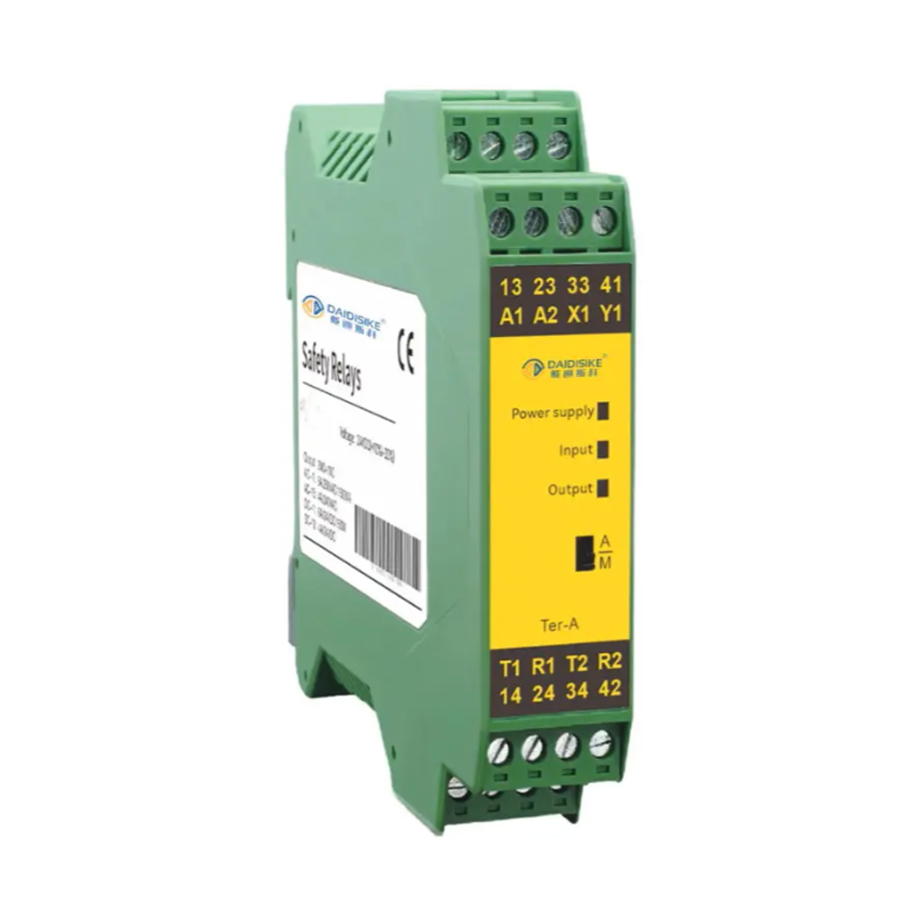
- Logic — a safety relay or safety PLC that evaluates the curtain's OSSD outputs. A properly applied dual-channel safety relay can also reach PL e.
- Output — the contactors or drive that actually remove power or motion. This is where functions quietly fail.
A single unmonitored contactor cannot be assigned a PL merely from that description. Its data and architecture may be inadequate for the required function. Two suitable contactors with correctly implemented feedback can form part of a higher-integrity output design, but reliability, diagnostics, common-cause measures, fault conditions and validation still have to be established. Adding a second contactor is not automatic PL e.
How much PL do you actually need?
The required PL is not a free choice — it comes from the risk assessment. ISO 13849-1 provides a risk graph that takes three parameters: the severity of the potential injury (reversible or irreversible), the frequency and duration of exposure to the hazard, and the possibility of avoiding the hazard once it occurs. Feed those in and the graph returns a required PL — the PLr — for that function.
In the ISO risk-graph method, the relevant severe-injury, frequent-exposure and difficult-avoidance combination can lead to PLr e. Record why each parameter was selected and check the applicable machine-specific standard. A robot cell, press or low-energy label alone does not fix every safety function's target. Select a design that meets the justified requirement and can be maintained and validated.
ISO 13849-1 or IEC 62061 — which one?
ISO 13849-1 is a practical option when the design and component data fit its methods, including designated architectures and manufacturer subsystem data. The choice should be made in the safety requirements specification, with the relevant machine standard and available validation evidence, not simply because a device carries a PL label.
IEC 62061 covers design, integration and validation of machinery safety-related control systems, including non-electrical technologies. The IEC catalogue now lists IEC 62061:2021 with Amendments 1:2024 and 2:2026. It does not itself cover designing complex programmable electronic subsystems. Use the selected edition's rules when integrating PL- or SIL-assessed subsystems; avoid both arbitrary formula mixing and the incorrect claim that cross-standard subsystem integration is always prohibited.
Common mistakes
Reading the component label as the function rating. Covered above, and worth repeating because it is that common. PL e on a curtain box is a capability, not a result.
Skipping the CCF checklist. Two channels that share a power supply, a cable route, or an environmental weakness can fail together. CCF scoring exists to catch that. A calculation that shows Category 3 architecture but never scores CCF is incomplete.
Forgetting the output stage. Engineers lavish attention on the sensor and the logic and then wire the result to a single unmonitored contactor. The output is a full subsystem and needs its own treatment — usually two monitored contactors with EDM feedback. Our light curtain and safety relay wiring guide shows the EDM loop in practice.
Ignoring response time. The PL tells you how reliably the function works; it says nothing about howfast. Those are separate requirements. A perfectly PL e function still injures someone if it is mounted closer than the ISO 13855 safety distance allows. Reliability and timing are both mandatory — see our ISO 13855 safety-distance guide.
Where DAIDISIKE products sit
For a DQA light curtain or DA31 relay, request the exact model's safety manual and reliability data before assigning a subsystem capability. Do not assume DA31 has EDM or a particular reset mode without its manual. The engineering team can help identify product documentation; the integrator remains responsible for the function-level assessment.
The bottom line
Use PL/SIL bands to understand the reliability target, then evaluate the actual safety function under the selected method. Check subsystem integration, quantitative and qualitative measures, response time and validation. A function-level claim requires that evidence; it is not obtained by relabelling a component rating.
Primary references
ISO 13849-1:2023 defines the PL design framework. The current IEC 62061 consolidated edition identifies its machinery scope and amendments. OMRON safety-control guidance explains control reliability concepts and their application limits. Consult the complete applicable standard for a compliance assessment.