
DQA Safety Light Curtain (Type 4 Architecture, PL e / SIL 3-capable)
Long-range through-beam AOPD for guarding presses, shears, large machines and robot cells. Eight distance classes from 0.3–3 m (A) to 0.3–50 m (H), the full pitch range 10/14/20/25/30/40/80/200 mm to match finger–body protection, and 4–32 beams for protective heights of 50–3400 mm. Transistor output with single- or dual-output signal selection, 5-core or 7-core wiring.
Note on the ratings in the title: the “Type 4 Architecture, PL e / SIL 3-capable” wording in this product name is historical. DAIDISIKE has not published a type-examination certificate or a functional-safety report for the DQA series, so please do not use the title as evidence of an IEC 61496 Type 4 classification or of a PL e / SIL 3 rating in your risk assessment. Ask us for the current certificate covering the exact model you intend to order — if the documentation your application needs does not exist for this series, we will say so and point you to one where it does.
What the DQA Is and Where It Fits
The DQA is DAIDISIKE's long-range through-beam safety light curtain — a multiple-beam opto-electronic protective device (AOPD) designed with reference to IEC 61496 and to the machinery-safety standards ISO 13849 / ISO 13855. It extends the same 4–32-beam, 10–200 mm pitch structure used by the standard-range DQC series out to spans the DQC is not intended to cover: wide machine perimeters, gantry and truss machining centres, robot-cell fencing, and warehouse or dock openings. The DQA offers a wider pitch range (10–200 mm in eight standard steps) than competitors such as Omron's F3SG-SR, Keyence's SL-V, SICK's deTec4 and Pilz's PSEN op series, and a deeper distance-class catalogue — eight classes from 0.3–3 m up to 0.3–50 m.
One point to settle before you specify: DAIDISIKE does not publish a type classification (Type 2 / Type 4) or a performance level for the DQA series, so this page does not claim one. If your risk assessment under ISO 12100 / ISO 13849-1 puts the application at a level that requires a documented Type 4 / PL e / SIL 3 device, either request the current test documentation from the factory or specify the DQT4 series, which is catalogued with that rating. The physical and electrical data is a different matter — the DQA catalogue does publish it: a ≤ 15 ms response time, IP65 aluminium housing, DC 12/24 V supply at ≤ 200 mA, and a −10 to +40 °C operating range, so those figures can go straight into your ISO 13855 safety-distance calculation.
The DQA part number encodes the build: DQA + beam count + "/" + beam pitch + "-" + protective height, so DQA32/10-310 reads straight off as 32 beams at 10 mm pitch giving a 310 mm protected height. Protective height is always (beam count − 1) × pitch — the distance from the first beam to the last beam, which is the figure that goes into your guarding layout. Above 32 beams, the catalogue directs you to the DQT series.
Product Highlights
- Eight distance classes A…H — 0.3–3 m, 6 m, 10 m, 15 m, 20 m, 25 m, 30 m and 50 m, selected at order time
- Full pitch range retained at long range — all eight pitches (10 to 200 mm) are available, so a long span does not force a coarse resolution
- 4–32 beams per pitch, protective heights 50–3400 mm (H = (n − 1) × K); above 32 beams the DQT series takes over
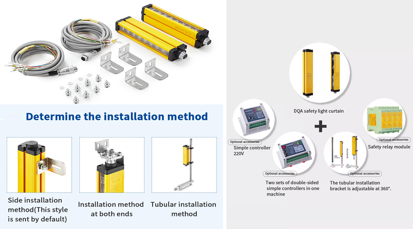
- Dedicated long-span mounting: DQA-01 / DQA-02 two-end brackets in addition to the common DQCA-01/02/03/05 set
- Transistor output with single- or dual-output signal selection; 5-core or 7-core wiring
- Easy integration with the DA31 safety relay or a safety PLC (EDM, manual/auto reset)
- Through-beam AOPD designed with reference to IEC 61496 and the machinery-safety standards ISO 13849 / ISO 13855; no type class or performance level is published for this series — confirm with the factory before use in a rated safety function
Values represent typical DQA series capabilities. For exact ratings on a specific build, refer to the delivered datasheet and unit label.
Resolution & Application Guide
| Resolution (K) | Typical Application |
|---|---|
| 10 / 14 mm | Finger protection — power presses, stamping fixtures, close-guarded operations |
| 20 / 25 mm | Palm / hand protection — press brakes, robot cell access, manual feed stations |
| 30 / 40 mm | Hand / arm presence — automated assembly, AS/RS aisle entry |
| 80 / 200 mm | Body presence — wide aisles, perimeter zones, large-equipment access |
Protective height H = (n − 1) × K, where n is the beam count. Overall mechanical length L follows the drawing rule L = P + H + J + end allowances. See the auto-generated spec tables below for every standard combination.
DQA vs Omron F3SG-SR vs Keyence SL-V vs SICK deTec4
The DQA competes head-on with the established Tier-1 European and Japanese safety-light-curtain brands. Side-by-side on the spec sheet:
| Item | DAIDISIKE DQA | Omron F3SG-SR | Keyence SL-V | SICK deTec4 |
|---|---|---|---|---|
| Published type / performance level | Not published for this series — see DQT4 for a catalogued Type 4 unit | ✓ (vendor cert.) | ✓ (vendor cert.) | ✓ (vendor cert.) |
| Response time (typ.) | ≤ 15 ms | ≤ 10 ms | ≤ 10.6 ms | ≤ 16 ms |
| Resolutions available | 10 / 14 / 20 / 25 / 30 / 40 / 80 / 200 mm | 14 / 25 / 30 / 45 mm | 14 / 25 / 35 / 45 mm | 14 / 30 / 40 mm |
| Max detection distance | Up to 50 m (class H) | Up to 20 m | Up to 15 m | Up to 19 m |
| Housing IP rating | IP65 | IP65/IP67 | IP65/IP67 | IP65/IP67 |
| Output | Transistor, single or dual output signal | Dual OSSD, PNP | Dual OSSD, PNP | Dual OSSD, PNP |
| Mounting brackets | DQCA-01/02/03/05 + DQA-01/02 two-end mounts | Proprietary | Proprietary | Proprietary |
Where the DQA differentiates: a broad resolution count (8 standard steps — useful for retrofits where matching the original resolution exactly avoids re-calculating safety distance) and maximum detection distance (up to 50 m in class H — relevant for wide press lines and AS/RS aisles). Where the competing units are ahead on paper: they publish certified type/performance-level ratings that DAIDISIKE has not published for the DQA series. If your specification depends on those ratings, obtain them from the factory in writing, or specify the DQT4 series. Please verify current specifications against each manufacturer's published datasheet.
How to Configure Your DQA — Seven-Step Selection Guide
The DQA is a configurable product family, not a single SKU. Walk through these seven steps to land on the right part number:
Step 1: Determine Protection Resolution (K)
ISO 13855 maps body part to required resolution. 14 mm finger protection — required for high-risk press-brake and stamping operations. 20-30 mm hand/wrist — robot cells, fixture access. 40-80 mm whole-body presence — aisle and large equipment perimeters. The smaller the K, the closer you can stand to the hazard (smaller C constant in the safety-distance formula).
Step 2: Calculate Protective Height (H)
H = (n − 1) × K, where n is the beam count. The DQA spec table lists every standard combination of K and H — pick the row that covers your hazard's full vertical reach. Common heights are 150 mm (finger protection on fixtures) to 1800 mm (full body for press operators).
Step 3: Pick the Distance Class (Range)
DQA distance classes go A through H: A=3 m, B=6 m, C=10 m, D=15 m, E=20 m, F=25 m, G=30 m, H=50 m. Pick one class above the actual emitter-to-receiver distance you'll mount at — the headroom keeps the optical signal strong against dust, smoke, and minor misalignment over the years.
Step 4: Choose Output Type (NPN or PNP)
All four transistor combinations are catalogued as order codes: A = NPN normally-closed, B = PNP normally-closed, C = NPN normally-open, D = PNP normally-open, with A the default when nothing is specified. Code J gives a volt-free internal relay output instead (AC 250 V 10 A / DC 30 V 16 A). PNP is the global default outside Asia; NPN is common on Japanese and older Chinese controls.
Step 5: Select the Wiring
The DQA is wired with 5-core or 7-core cable, matching the single- or dual-output signal choice made in step 4. Confirm connector style with the factory when you place the order.
Step 6: Choose the Mounting Accessories
The common DQCA-01/02/03/05 brackets cover standard mounting. For long spans, add the dedicated DQA-01 / DQA-02 two-end mounting brackets — they hold both ends rigidly, which makes beam alignment across a long emitter-to-receiver span far easier to set and to keep.
Step 7: Check the Beam-Count Ceiling
The DQA is catalogued from 4 to 32 beams per pitch. If your protective height needs more than 32 beams at the pitch you have chosen, the DQT series is the catalogue's designated long-range alternative (up to 72 beams).
Not sure which combination to pick? Send a short description of your machine and operating conditions through the contact form — our engineering team will respond with a specific part-number recommendation, usually within 24 hours.
DQA Technical Parameters
| Category | Item | Typical Value / Option | Notes |
|---|---|---|---|
| Optical | Principle | Through-beam IR LED, modulated | Emitter/receiver pair |
| Light source | Modulated infrared LED | Catalogue: 调制红外LED | |
| Resolutions (beam pitch) | 10 / 14 / 20 / 25 / 30 / 40 / 80 / 200 mm | Finger → body presence | |
| Detection accuracy | 18 / 22 / 28 / 33 / 38 / 48 / 88 mm (for 10 / 14 / 20 / 25 / 30 / 40 / 80 mm pitch) | Smallest object reliably detected | |
| Beam count | 4–32 | Above 32 beams, use the DQT series | |
| Protective height | H = (n − 1) × K; 50–3400 mm | First beam to last beam | |
| Detection distance | Class A 0.3–3 m up to class H 0.3–50 m | A…H distance classes (see below) | |
| Response | ≤ 15 ms | Catalogue value — use this in your ISO 13855 calculation | |
| Electrical | Outputs | NPN / PNP transistor, 500 mA max, saturation voltage < 1.5 V; polarity, short-circuit and overload protection | Single- or dual-output signal selection |
| Relay (passive) output rating | AC 250 V 10 A; DC 30 V 16 A | Built-in volt-free relay build (J output code) | |
| Wiring | 5-core or 7-core | Circular aviation socket; 5-core emitter + 5-core receiver as standard | |
| Supply voltage | DC 12 V / 24 V; AC 110–220 V on the relay-output build | Per catalogue technical-parameter table | |
| Current consumption | ≤ 200 mA | Per catalogue technical-parameter table | |
| Indicators | Emitter: power indicator (red). Receiver: output indicator green = all beams clear, red = beam blocked | Front status LEDs | |
| Mechanical / Environment | Body section | 35 × 51 mm × L | L = emitter / receiver length |
| Housing material | Aluminium alloy body, ABS reinforced-nylon end caps | Catalogue: 铝合金,端盖 ABS 增强尼龙 | |
| Ingress protection | IP65 | Per catalogue technical-parameter table | |
| Operating temp. | −10 to +40 °C (non-freezing) | Storage −25 to +55 °C | |
| Humidity | 35–85 % RH operating | 35–95 % RH storage | |
| Ambient light immunity | 10,000 Lux (incidence angle ≥ 5°) | Incandescent 3,000 Lx / sunlight 10,000 Lx on the receiving surface | |
| Compliance | Standards | Through-beam AOPD designed with reference to IEC 61496; safety distance per ISO 13855 | No type class (Type 2/4) or performance level is published for this series — confirm with the factory |
| Notes | Markings per delivered unit | Contact us for country-specific approvals |
Distance classes A…H: A 0.3–3 m · B 0.3–6 m · C 0.3–10 m · D 0.3–15 m · E 0.3–20 m · F 0.3–25 m · G 0.3–30 m · H 0.3–50 m (selected variants).
DQA Detailed Specifications (Resolution-by-Resolution)
| K (mm) | Beams n | Protective Height H (mm) | Model Example | Range |
|---|---|---|---|---|
| 10 | 6 | 50 | DQA06/10-50 | A…H (0.3–3 m … 0.3–50 m) |
| 10 | 8 | 70 | DQA08/10-70 | A…H (0.3–3 m … 0.3–50 m) |
| 10 | 10 | 90 | DQA10/10-90 | A…H (0.3–3 m … 0.3–50 m) |
| 10 | 12 | 110 | DQA12/10-110 | A…H (0.3–3 m … 0.3–50 m) |
| 10 | 14 | 130 | DQA14/10-130 | A…H (0.3–3 m … 0.3–50 m) |
| 10 | 16 | 150 | DQA16/10-150 | A…H (0.3–3 m … 0.3–50 m) |
| 10 | 18 | 170 | DQA18/10-170 | A…H (0.3–3 m … 0.3–50 m) |
| 10 | 20 | 190 | DQA20/10-190 | A…H (0.3–3 m … 0.3–50 m) |
| 10 | 22 | 210 | DQA22/10-210 | A…H (0.3–3 m … 0.3–50 m) |
| 10 | 24 | 230 | DQA24/10-230 | A…H (0.3–3 m … 0.3–50 m) |
| 10 | 26 | 250 | DQA26/10-250 | A…H (0.3–3 m … 0.3–50 m) |
| 10 | 28 | 270 | DQA28/10-270 | A…H (0.3–3 m … 0.3–50 m) |
| 10 | 30 | 290 | DQA30/10-290 | A…H (0.3–3 m … 0.3–50 m) |
| 10 | 32 | 310 | DQA32/10-310 | A…H (0.3–3 m … 0.3–50 m) |
Model rule: DQA + beam count (2 digits) + "/" + beam pitch + "-" + protective height (e.g., DQA08/40-280). Distance classes A…H are selected at order time; A:0.3–3 m (std) · B–H up to 50 m. Above 32 beams, use the DQT series. For exact dimensional constants (P/J) use the drawing in the datasheet.
Where DQA Is Already Working — Field-Tested Applications
Stamping Press / Punch Press Guarding
The DQA 14 mm finger-protection variant is a standard choice for power-press guarding under ISO 16092. Mount the emitter/receiver pair across the die-access opening and calculate the ISO 13855 safety distance from your machine's measured stopping time plus the curtain's ≤ 15 ms response time.
Press Brake / Shear / Forming Equipment
Press brakes use the DQA 20-25 mm palm/wrist resolution along the front working edge of the brake. Together with a foot-pedal two-hand control and a safety relay running EDM feedback, the system is fully compliant with ISO 16092-3 for press brakes and ISO 16092-4 for shears. For laser-guard alternative on press brakes see the DKE-L3 laser-guard product page.
Robot Cell Perimeter
Around collaborative robot cells, the DQA 30-40 mm hand/arm resolution forms the perimeter break-line. Operator entering the cell breaks the beam, robot transitions to safe-stop, exit clears the beam, manual reset on the safety relay re-enables motion. Pairs with the DA31 safety relay module for a complete certified loop.
Aisle and Zone Access Protection
For wide doorways into automated material-handling zones or pallet-stacker cells, the DQA 80-200 mm body-presence variant covers the full opening with a single emitter/receiver pair. Long-range H-class (up to 50 m) handles cross-bay protection without intermediate units.
Automated Storage and Retrieval Systems (AS/RS)
AS/RS aisles use DQA presence-detection variants to mute the safety stop when a pallet legitimately enters the cell and re-arm immediately on operator presence. Muting is implemented in the safety relay logic, not on the DQA itself — keeping the certification intact.
Assembly Line Operator Stations
Single-operator assembly stations with manual loading + automated operation use the DQA 14-20 mm finger/hand resolution to ensure the operator's hands are clear before the cycle starts. Common pairing with two-hand palm buttons for cycle initiation.
Safety distance reference (ISO 13855): S = K × T + C. Use our interactive calculator at /iso-13855-safety-distance-calculator to plug in your machine's stopping time and confirm the mounting distance for any of the resolutions above.
What Type 4 / PL e / SIL 3 Actually Mean — Compliance Plain English
The three ratings sound interchangeable but come from different standards bodies with different historical reasons. They all converge on the same practical question: can this safety function be trusted to stop the machine when a person enters the danger zone?
- Type 4 (IEC 61496-1) — the rating specific to ESPE (electro-sensitive protective equipment) like light curtains. Requires dual-channel architecture with cross-monitoring, where any single internal fault causes the OSSD outputs to switch to the safe state (off). DAIDISIKE has not published a Type 2 or Type 4 classification for the DQA series, so this page does not state one — the DQT4 series is the catalogued Type 4 product.
- PL e (ISO 13849-1) — the rating for the entire safety function, including the curtain, the safety relay, the contactors, and the wiring. PL e is the highest level (above PL a/b/c/d), defined by a combination of category (architecture), MTTFd (mean time to dangerous failure), DC (diagnostic coverage), and CCF (common-cause failure). Every element of the chain must contribute documented numbers — the curtain, the safety relay (DA31 or equivalent) and the contactors. No PL figure is published for the DQA series; request it from the factory if your calculation needs one.
- SIL 3 (IEC 61508 / IEC 62061) — the corresponding rating in the IEC framework, used more in process industries and increasingly cross-referenced with ISO 13849 in machinery. SIL 3 has a probability-of-failure-on-demand target of 10⁻⁴ to 10⁻³ per demand. As with PL, no SIL figure is published for the DQA series — obtain it from the factory, or use the DQT4 series where the rating has to be documented.
For a typical machinery installation in the EU, satisfying ISO 13849-1 is the path of least resistance: every element of the chain supplies its documented reliability numbers, the safety relay documentation provides matching figures, and a competent risk assessment under ISO 12100 + ISO 13849-1 documents and validates the complete chain. Ask DAIDISIKE for the DQA test documentation, or specify the DQT4 series, before you rely on a stated PL/SIL value. See our PL/SIL quick-reference article for the verification logic and what the actual calculations look like.
Frequently Asked Questions
What's the difference between Type 2 and Type 4 safety light curtains, and which do I need?
Type 2 is single-channel with diagnostics — adequate for low-risk machinery where the risk assessment justifies PL c / Cat 2 safety. Type 4 is dual-channel with cross-monitoring, fault-detection-on-itself, and PL e / SIL 3 capability when integrated correctly — required for high-risk machinery (stamping presses, shears, press brakes, robot cells with serious crush or shear hazards). DAIDISIKE has not published a type classification for the DQA series. If a risk assessment under ISO 12100 / ISO 13849-1 puts your application at PL d or PL e, specify the DQT4 series — it is the catalogued Type 4 product — or obtain the DQA test documentation from the factory first. The integrator must still verify the complete safety function during commissioning.
Can the DQA directly replace an Omron F3SG-SR, Keyence SL-V, or SICK deTec?
Mechanically, in many cases. Match the beam pitch, the protective height and the required detection distance to the unit being replaced. Two checks matter before you commit: (1) compare response times — the DQA is catalogued at ≤ 15 ms, so if the unit you are replacing was faster, re-run the ISO 13855 safety distance before you reuse the existing mounting position; (2) where the original unit carried a certified Type 4 / PL e rating, confirm the equivalent documentation, or specify the DQT4 series, which is catalogued with that rating. Contact our engineering team with the existing part number for a direct replacement recommendation.
How do I calculate the safety distance using ISO 13855?
Formula: S (mm) = K × T + C. K is the body-approach speed (2000 mm/s for hand approach toward the danger zone). T is total system stopping time in seconds — light curtain response (≤ 15 ms for the DQA) + safety relay response (typically 20-40 ms) + machine stopping time (the biggest term, measured by overrun test, typically 100-300 ms for hydraulic systems). C is the intrusion-depth constant: 8 × (resolution − 14) mm for resolutions above 14 mm, capped at 850 mm; or 128 mm for whole-body protection (40+ mm resolution). Use our interactive calculator at /iso-13855-safety-distance-calculator for the full math with a worked example for your specific machine.
What does PL e and SIL 3 mean — are they the same thing?
Different rating systems, similar levels. PL (Performance Level) e is defined in ISO 13849-1 and rates the safety function's reliability based on category, MTTFd, DC (diagnostic coverage), and CCF (common-cause failure). SIL (Safety Integrity Level) 3 is defined in IEC 61508 / IEC 62061 with a similar but mathematically different framework. For practical purposes, a safety function rated PL e is equivalent to SIL 3 in terms of reliability targets. Neither figure is published for the DQA series, so neither is claimed here — request the test documentation from the factory, or specify the DQT4 series where the rating has to be documented. Final classification of the complete safety chain is validated by the integrator during commissioning.
What's the typical lifetime of a DQA in industrial use?
The DQA is electronics-only — no mechanical contacts to wear. DAIDISIKE does not publish an MTBF or service-life figure for the series, so none is quoted here; ask the factory if your specification requires one. What matters operationally is the verification regime rather than calendar age: periodic test-rod verification every 6-12 months under ISO 13855, plus a check that the housing seal and alignment are intact, keeps the safety function validated.
How does optical synchronization work and when do I need wired sync instead?
Optical synchronization means the emitter and receiver share the modulated-light signal that the system already uses for beam detection — the first beam pair carries the sync clock, and all subsequent beams scan in lock-step. No extra cable is needed between emitter and receiver besides the alignment of the optical pair itself. This works cleanly for 95% of installations. Wired sync — a dedicated synchronization wire between emitter and receiver — is offered as an option for unusual environments: very high EMC noise floors (large servo-motor banks), unusual ambient-light patterns (welding flash, halogen flood), or installations where the optical-sync first-beam alignment is too constrained by mechanical layout. The DQA catalogue data does not state which synchronization method the series uses — confirm it with the factory when you order, especially on long spans.
Do I need to retest the safety distance every time I change the safety relay or the contactor?
Yes — but the test is fast. ISO 13855 considers the entire stop-chain from light-curtain output through to actuator de-energization. Replacing the safety relay with a different model can change the T value by 10-30 ms, which shifts the calculated safety distance by 20-60 mm. The recommended practice: re-measure the machine's actual stopping time (with the new relay/contactor in place) using a calibrated stop-time analyzer, then plug the new T value into the safety-distance formula. If the result is bigger than your physical mounting distance, you need to move the light curtain back to stay compliant. Document the test in your safety file.
PDF & 3D CAD Downloads
Browse all downloadsDQA / DQT Safety Light Curtain Series Brochure
3D CAD MODELS
Find the file for your exact model
Open the download center with the named series selected. Search your full model, check the file details and download the matching STEP file.
Confirm the document and CAD file match your exact ordered version before installation or mechanical design. Contact us if your model is not listed.
Specs reviewed by Engineer Cai, Senior Application Engineer. See certificates.
Safety Light Curtain — Customer Cases
Real installations from DAIDISIKE clients. Click any case to view in full. Filter by scenario to quickly find a similar setup.
Press Guarding · Safety Light Screen
Robot Cell · Safety Light Barrier
Anti-Interference · Adjacent Installations
Access Gate · Guarding Light Curtain
Workstation · Compact Light Screen
Packaging Line · Machine Safety Light Curtain
Large Opening · Multi-Beam Safety Device
Assembly Conveyor · Photoelectric Light Curtain
Detection · Safety Light Array (Measurement)
Area Guarding · Safety Light Grid