
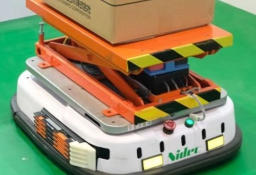
Walk through almost any modern warehouse or large plant and you will see them: low, flat vehicles gliding down aisles, carrying racks, totes, or pallets, threading between people who barely look up any more. The fleet has grown fast. The safety engineering, in a lot of facilities, has not quite kept pace.
A mobile robot is, in safety terms, a moving machine operating in a space that may be shared with people. Unlike a fixed machine, it often cannot be separated from every travel aisle by fencing. Risk reduction therefore combines vehicle-mounted protection with operating-zone controls. This article focuses on how the safety laser scanner contributes, the standards that govern the application, and the boundary between safety and navigation LiDAR.
AGV, AMR — and why the safety job is the same
A quick definition, because the terms get used loosely. An AGV, automated guided vehicle, follows a fixed route — historically a wire, a magnetic tape, or a line of reflectors. An AMR, autonomous mobile robot, navigates freely: it builds a map, localizes itself on it, and plans its own path, routing around obstacles as it goes.
The distinction matters for fleet software and flexibility. For safety, it matters less than people expect. Both move mass through shared space; both must stop before contact. An AMR's free navigation makes its path harder to predict, which puts a little more weight on getting the field design right. The same risk-assessment discipline applies to both. A certified safety laser scanner is one common way to monitor the direction of travel, but it is not a substitute for assessing the complete vehicle, braking system and operating zone.
Protective field and warning field
A safety laser scanner sweeps a laser beam across a horizontal plane, usually a wide arc in front of the vehicle, and measures the distance to whatever it hits. It is configured to monitor two kinds of zone.
The protective field is the one that matters most. Anything that enters it — a foot, a leg, a dropped box — causes the safety outputs to request the validated stop. The warning field is larger and sits beyond the protective field. A warning-field intrusion can request a slowdown, an audible warning, or a light, but the warning field is not itself a safety-rated protective function. Any safety-related speed change still has to be implemented and validated by the safety control system.
The single rule that governs all field design: the protective field, measured in the direction of travel, must always be at least as long as the vehicle's stopping distance at its current operating condition — plus the response-time and measurement allowances required by the device instructions and the application risk assessment. If the field does not cover the validated stopping performance, detection alone cannot prevent contact.
Speed-dependent field switching
Stopping performance changes with speed, load, braking condition, controller response and the floor. A single field sized for the most demanding condition can cause unnecessary stops in slow, congested areas; a field sized only for slow operation cannot be used for a faster condition.
One solution is speed-dependent field switching. A safety-related control system selects a pre-configured monitoring case using safely evaluated inputs such as speed, direction or steering state. Typical field shapes include:
- Fast, straight ahead — a long, relatively narrow protective field reaching well down the aisle.
- Slow — a much shorter field, so the robot can work close to people and racking without nuisance stops.
- Turning — a field covering the swept path of the vehicle and its load, including outer corners and any rear swing.
Every field used must cover the validated stopping performance for its operating condition. The selection inputs, transition timing, field dimensions and fallback state all belong to the safety function; dynamic selection alone does not make the arrangement safe.
The standards that apply
Several standards address different parts of mobile-robot safety. The applicable set and editions depend on the market, machine scope and risk assessment; the references below are not a blanket compliance checklist:
| Standard | What it covers |
|---|---|
| ISO 3691-4 | Safety requirements and verification for driverless industrial trucks and their systems, including AGVs and AMRs within its scope. |
| ANSI/RIA R15.08-1 / ANSI/A3 R15.08-2 | North American requirements for the industrial mobile robot, then its system and application. |
| IEC 61496-3 | Requirements for AOPDDR electro-sensitive protective equipment that detects people using diffuse reflection. |
| ISO 13849-1 / IEC 62061 | Methods used to evaluate the safety-related control function's required Performance Level or SIL. |
That last row is worth a note. The scanner being a certified protective device is necessary but not sufficient — the whole stop function, from scanner to brake, has a Performance Level that has to meet what the risk assessment requires. If that phrase is unfamiliar, our companion guide to Performance Level and SIL covers it properly.
Navigation LiDAR is not a safety scanner — be clear on this
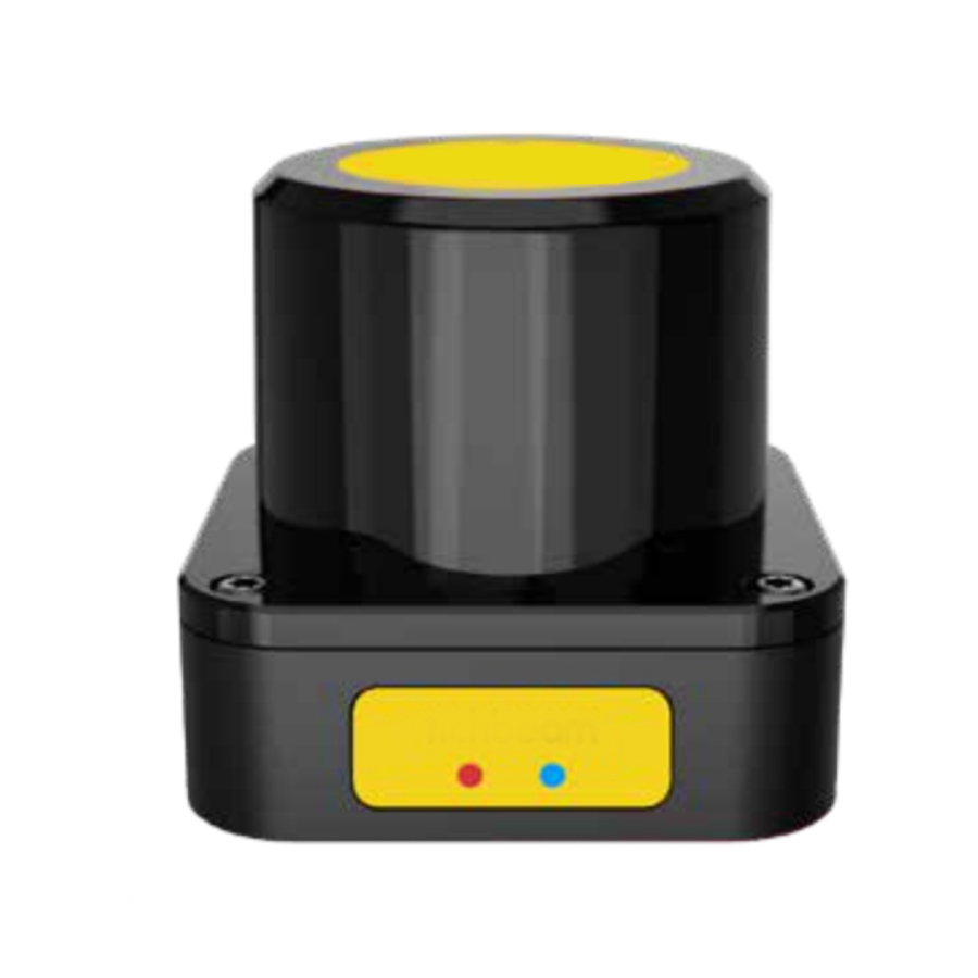
This is the distinction that gets blurred most often, and it is worth being blunt about. A navigation or obstacle-avoidance LiDAR exists to help a robot map its surroundings and route around obstacles. It is an operational sensor, and a good one can be very capable.
A certified safety laser scanner is a different class of device. IEC 61496-3 specifies requirements for AOPDDR protective equipment, but the type and safety performance remain model-specific. A safety scanner has documented diagnostics, failure behaviour and safety outputs for its declared rating. An ordinary navigation LiDAR may detect obstacles reliably in normal operation, but it does not inherit those safety claims merely because it uses similar scanning technology.
Many mobile robots therefore use both device classes: a navigation LiDAR for path planning and mapping, and a certified safety scanner dedicated to the protective function. One device can serve both roles only when the relevant functions and interfaces are explicitly covered by its documentation and the complete safety function has been validated.
Mixed traffic — the hard part
A vehicle-mounted scanner addresses only hazards covered by its validated fields. It cannot by itself prevent a manually driven forklift from striking the robot, control every side approach, or resolve all conflicts at a blind corner.
Mixed-traffic aisles — robots, forklifts, and pedestrians all sharing the floor — require a system-level assessment. Measures can include segregated lanes, controlled crossings, conservative speeds, sightlines and traffic rules. Where a robot route crosses a pedestrian walkway, the risk assessment may also require fixed protective equipment, such as a correctly selected light curtain or safety scanner, because the vehicle-borne scanner cannot control every hazard around the intersection.
Common mistakes
Field cases that do not match the operating states. Every required speed, direction and steering condition needs a validated protective response. Additional field cases help only when their dimensions, safe selection signals and transitions are verified together.
Ignoring the turn. A vehicle turning can sweep its rear and corners beyond a forward field. Depending on the geometry and risk assessment, a safely selected turning field, additional scanner coverage or another protective measure may be required.
Low obstacles and overhangs. A 2D scanner monitors a plane at its configured mounting height. Loads or structures above that plane, and objects beneath it, need separate treatment in the vehicle and load design.
Stopping distance measured once and never again. Brakes wear, loads change, floors get slippery. The stopping distance that justified the field configuration at commissioning should be re-verified periodically — especially after any change to vehicle mass or top speed.
Where DAIDISIKE fits — honestly
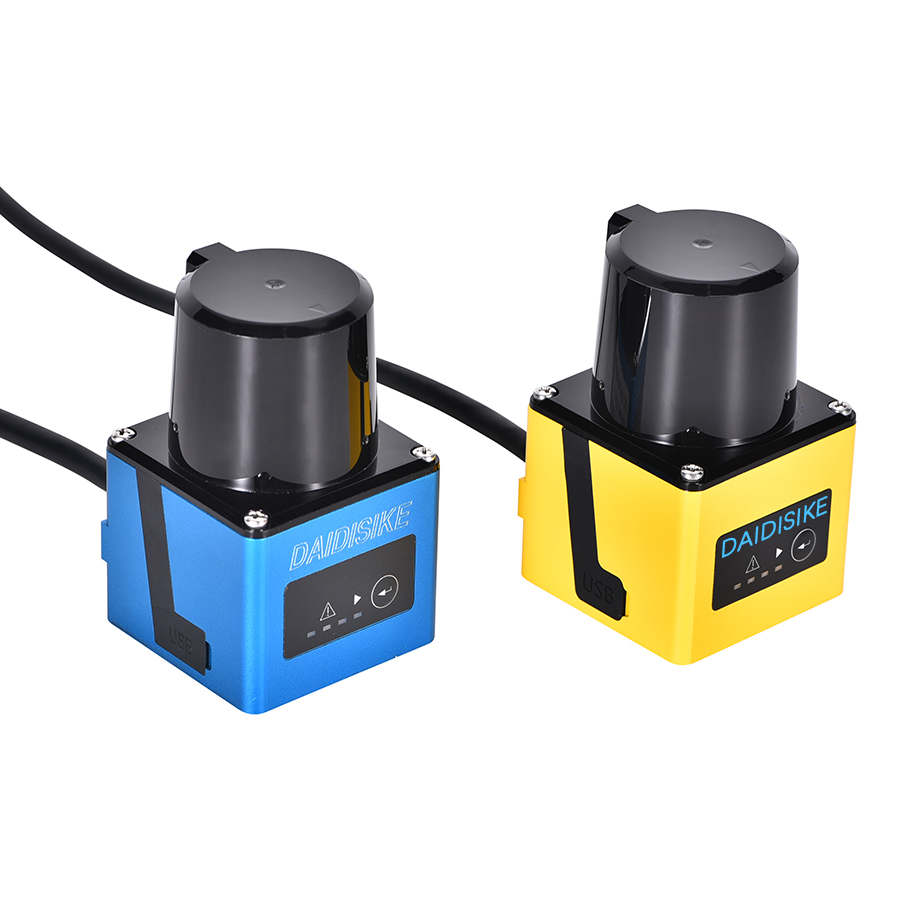
DAIDISIKE's ST27 safety laser scanner is the personnel-protection model in this application: Type 3, Category 3 / PL d and SIL 2, with safety outputs for integration into the validated stop function. The certification scope and current model documentation still have to be checked for the exact ordered configuration and target market.
The DLD, SDLD, DLDS and JPTG families serve navigation, distance measurement or ordinary obstacle-avoidance roles; they are not certified personnel-protection scanners. Examples include the DLD05A3 / DLD20A5 obstacle-avoidance laser radar and DLD30T-5N. Compare the intended roles in our industrial LiDAR scanner range before selecting a device for an AGV or AMR architecture.
If you are specifying a mobile robot and need to separate the navigation, obstacle-detection and personnel-protection functions, send the risk-assessment requirements and interface list to our engineering team. Model selection must be based on documented function and certification scope, not the shared word “LiDAR.”
The bottom line
A protective field is useful only when it covers the validated stopping performance for the active operating condition. Keep navigation and personnel-protection functions distinct, validate every field transition, and assess the complete operating zone — not just the sensor mounted on the robot.
Primary references checked
- ISO 3691-4:2023 — scope and safety requirements for driverless industrial trucks and their systems.
- IEC 61496-3:2025 — AOPDDR electro-sensitive protective equipment.
- A3 robot-safety standards — official R15.08 Part 1 and Part 2 descriptions.
- SICK S3000 operating instructions — manufacturer guidance on mobile protective-field length and speed-dependent monitoring cases.
These references define scope and engineering principles; they do not replace the current product manual, certificate set, machine risk assessment or on-site validation.