
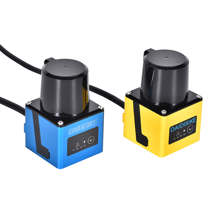
Consider a common selection question. An integrator has an autonomous vehicle, or a robot cell, or an AGV docking station, and somewhere in the bill of materials there is a laser scanner. The question, dressed up in different ways, is always the same: is the cheap one good enough? The honest engineering answer is that “good enough” is not the right axis. The question is whether the device has the documented safety function required by the risk assessment, and whether the complete stop chain can meet that requirement. A certificate is evidence about its stated scope, not permission to use any layout.
This article is the long version of that conversation: what the IEC 61496 family actually says, what the Type test actually tests, why dual OSSD and self-monitoring matter, what detection capability really means on a datasheet, and why a navigation LiDAR — even a very good one — sits the wrong side of the line.
The IEC 61496 family in one paragraph
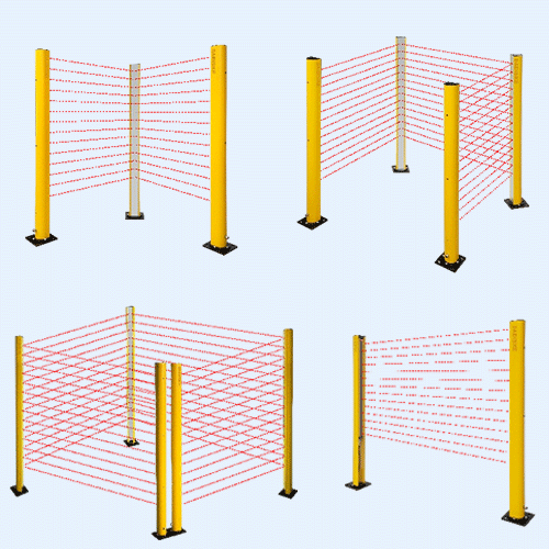
IEC 61496 is a multi-part standard for non-contact electro-sensitive protective equipment — ESPE for short. Part 1 is the umbrella: general requirements and the type tests every ESPE has to pass regardless of technology. The particular parts each cover one device family. IEC 61496-2 is for AOPDs — active opto-electronic protective devices, which is the official name for safety light curtains and light beams. IEC 61496-3 is for AOPDDRs — the diffuse-reflection variant, which is the official name for safety laser scanners. IEC 61496-4 is for VBPDs — vision-based protective devices, the safety-rated camera systems. The current Part 1 edition is the 2020 fourth edition; the current Part 3 edition is 2025 (a technical revision of the 2018 third edition), which is the document we will mostly mean by “Part 3” below.
The official IEC 61496-3:2025 scope covers both 2D and 3D detection zones, but not a one-dimensional optical proximity measurement. It also excludes outdoor application tests. Do not transfer a certificate for one model, edition or operating condition to another without checking its actual scope.
Type 2, Type 3, Type 4: what the classes really mean
The Type classification in IEC 61496-1 is the single most misunderstood thing in this corner of machine safety. It is not a quality grade and it is not a marketing rank. It is a description of how the device behaves under a single fault and how thoroughly it monitors itself.
- Type 2. Relies on a periodic test — as specified by the device and application — to detect a dangerous fault. Between tests, a single fault could go undetected. Suitable up to PL c / SIL 1 in a complete safety function.
- Type 3. Has defined fault-detection and safe-response requirements. Widely used laser-scanner implementations declare PL d / SIL 2. The certificate and safety manual define the model’s permitted use.
- Type 4. The most demanding fault-detection requirements in the standard. A single fault must never lead to a loss of the safety function. Suitable up to PL e / SIL 3. Type 4 light curtains are common; a conventional Type 3 scanner with PL d / SIL 2 cannot be relabelled PL e / SIL 3. That is a limit of the stated device capability, not a claim about every possible area-protection architecture.
The two practical points to hold on to: first, a Type-3 scanner with a declared PL d / SIL 2 capability does not by itself establish PL e / SIL 3, even when connected to higher-rated logic. Second, the Type rating is for the device alone — the achieved PL or SIL of the full safety function depends on the logic and the actuator as well. We unpack the second point in our companion piece on Performance Level vs SIL.
What the type test actually tests
People talk about a scanner being “tested to IEC 61496-3” as if that were a single test. It is not. The type test is an assessment programme built from the general requirements in Part 1 and the particular requirements in Part 3, and it has four families of content.
1. Functional behaviour
The lab verifies that every declared safety function does what the manual says it does. Does the protective field actually stop the OSSDs when a defined object enters it, across the declared working range, against backgrounds of declared reflectivity? Is the response time at or under the declared figure under worst-case scanning geometry? Does each declared option — switchable field sets, encoder inputs, reference-boundary monitoring — meet its specification?
2. Detection capability
IEC 61496-3:2025 covers a minimum detectable object size of 30–200 mm. The individual scanner does not necessarily support that entire range. Check its stated test-object size, protective-field range, target conditions and response-time configuration together. A 70 mm setting used for leg detection is not hand protection. There is no universal 150 mm mounting height implied by the standard scope: mounting, reach-under risks and separation distance must be checked against the model instructions and applicable installation requirements.
3. Single-fault behaviour
For a Type-3 scanner, this is the heart of the standard. The lab injects single faults — an open circuit on an OSSD, a stuck output, a partial loss of the laser pulse, an internal memory corruption — and verifies that the device meets the required safe response and fault-detection behaviour. This is the test that, more than any other, separates a safety device from an ordinary sensor. An uncertified scanner is not architecturally incapable of being safe; it has simply never had to prove that it is.
4. Environmental immunity
The lab subjects the device to the full Part 1 environmental requirements and the relevant AOPDDR-specific influences: declared temperature and humidity conditions, mechanical stresses, electromagnetic immunity and optical interference. The selected test levels and acceptance criteria come from the applicable clauses, not a generic “industrial” label. IEC 61496-1 and Part 3 do not define EMC emission requirements. Nor does passing this device assessment establish suitability for every weather or condensation condition.
Dual OSSD, and why it matters
A common hard-wired scanner output topology uses two short-circuit-proof solid-state safety outputs — OSSDs — both of which must be active to authorise motion. The reason is exactly what you would expect. If one OSSD is stuck high or is shorted to 24 V by a damaged cable, the second one still drops, the safety logic sees the discrepancy when correctly integrated. The scanner may use brief test pulses to diagnose output faults; the receiving safety input must be compatible with those pulses and the specified timing. OSSDs are not the only possible certified interface: some scanners transmit safety status through certified safety communication. Ordinary Ethernet measurement data is not that interface. Follow the exact model’s connection and fault-response requirements rather than judging safety solely by connector count.
Self-monitoring: optical, electrical, microprocessor
Safety-related diagnostics can monitor the optical path, electronics, processing and safety outputs. The device must respond to relevant faults as required by its classification and declared functions. Do not infer a particular processor count or internal circuit from the Type number alone. For an installation, the useful evidence is the safety manual’s fault response, contamination limits, diagnostic messages and required checks, supported by the applicable assessment documents.
The application standard: IEC 62046 and ISO 13855
The device standard tells you what makes a scanner safe. The application standard tells you how to use it. IEC 62046:2026 covers the selection, positioning, configuration and commissioning of ESPE — including AOPDDRs — for the protection of persons in machinery applications. It works alongside ISO 13855, which gives the safety-distance calculation. The two together tell you how high to mount the scanner, how far the protective field has to extend in front of the hazard, what reach-over and reach-under cases you have to consider, and how to verify that the resulting installation actually stops the machine before a person can reach the danger zone. A scanner that meets Part 3 is necessary; the right integration and validation under the applicable application standards are separate work. The 2026 edition of IEC 62046 replaces the 2018 edition; confirm which editions and regional requirements apply to the project rather than altering an existing certificate’s cited edition.
For a practical installation sequence, continue to the factory anti-collision scanner integration guide. It addresses the application task; this page explains the device standard and the evidence to check first.
Why navigation LiDAR is not automatically safety-rated
This is the part of the conversation where someone usually objects: “but the navigation LiDAR we are using has centimetre accuracy and a long range — surely it is…” Accuracy alone does not answer the safety question.
A point-cloud interface or an ordinary switching output does not establish the safety function’s detection reliability, diagnostic behaviour or fault response. A navigation-only product must therefore remain outside the claimed personnel-protection chain unless the exact function has appropriate safety evidence. This is a distinction between documented functions, not a claim that all navigation sensors share the same electronics. A certified scanner can also supply non-safety navigation data; that extra stream does not replace its certified safety interface.
None of this makes a navigation LiDAR a bad product. It is built for a different job — mapping, localisation, path planning — and is generally excellent at it. The error is the substitution: pointing at a navigation point cloud and treating it as a safety device, because it looks like the same hardware and is cheaper. It is not the same device, and the people who write IEC 61496-3 know it.
Type 2 vs Type 3 vs Type 4 — at a glance
| Type | Fault detection | Conventional selection limit* | Typical use |
|---|---|---|---|
| Type 2 | Periodic test; single faults possible between tests | PL c / SIL 1 | Lower-risk access detection; some long-range AOPDDR perimeter use |
| Type 3 | Defined fault detection and safe response; verify model documentation | PL d / SIL 2 | Mainstream safety laser scanners; AGV/AMR onboard; area scanning |
| Type 4 | Highest fault detection; single fault must not lose function | PL e / SIL 3 | Common for light curtains; not a standard rating for laser scanners |
*This is a conventional ESPE selection summary, not a substitute for the applicable standard and exact model certificate. Check the declared Type, PL/SIL and application restrictions together, particularly for Type 2 AOPDDR implementations. The full safety function still needs its own assessment across the complete chain.
The certification process — the practical view
The manufacturer prepares a design dossier (architecture, fault analyses, software life-cycle evidence, environmental design rationales) and submits it together with production samples to an appropriate assessment body. Agree the standard editions, declared functions and evidence required for the target market before testing. A recognised test laboratory, an EU notified body and a North American certification body are not interchangeable labels. Their scope and the applicable market-access route must be checked for the product and jurisdiction.
Cost and lead time depend on that agreed scope, design maturity, samples, documentation and any retesting. This page does not assign an unsupported universal budget or schedule. Buyers should ask for the actual certificate, its covered model list and the corresponding safety manual, then verify document authenticity and restrictions with the issuer or manufacturer.
Certificate-to-application evidence checklist
| Check | Document to match | Do not assume |
|---|---|---|
| Identity and edition | Certificate scope, order code and applicable hardware/software versions | One family name covers every variant or later revision |
| Safety function | Declared Type, PL/SIL, safety output path and operating limits | A logo or ordinary point-cloud output proves a safe stop |
| Detection and environment | Model safety manual: field size, response time, target and environmental limits | Maximum detection range equals protective range, or IP rating proves freezer/outdoor use |
| Complete installation | Risk assessment, layout, stop-chain design and validation record | The sensor certificate certifies the machine or vehicle |
Where DAIDISIKE sits
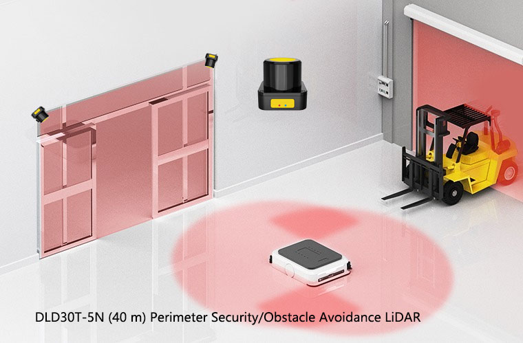
For completeness on our own side: the confirmed DAIDISIKE safety model is the ST27 safety laser scanner (Type 3, PL d, SIL 2). Request the certificate and safety manual for the ordered variant and validate its integration. In contrast, the DLD05A3 and SDLD-05A support ordinary onboard obstacle detection; the DLD20A5 handles perception scanning in the 20 m class; the DLD30T-5N is rated for 30 m at 90% remission and 10 m at 10% remission for perimeter monitoring. Those DLD and SDLD models are not presented as IEC 61496-3-certified personnel-protection devices. Their ordinary detection outputs must not be relabelled as safety OSSDs. We distinguish them here because readers may encounter both product classes on our site — but the cluster article you are reading is meant as an engineer’s reference to the standard itself, and that is what the rest of the page is about.
The bottom line
Check safety claims against the exact device and its assessed functions: detection capability, response time, fault behaviour, safety interface and environmental limits. IEC 61496-1 and Part 3 provide the device requirements; the machine or vehicle still needs a suitable safety architecture and application validation. An ordinary perception sensor is useful, sometimes excellent, but it cannot take the place of that documented protective function merely because its range is impressive.
Related reading
Industrial Safety LiDAR — Complete Reference
Engineering reference for fields, response time and integration; not a substitute for a model safety manual.
PL vs SIL
How Type 3 / Type 4 ESPE map to PL d / PL e and SIL 2 / SIL 3 in a full safety function.
How to Choose an Industrial LiDAR Scanner
Safety vs navigation, range, protective fields — the buyer-side companion piece.