
DDK-G Series Laser Displacement Sensor — 2 µm at 30 mm
A compact CMOS triangulation sensor with five reference distances from 30 to 250 mm — including the 85 and 120 mm grades most series skip — so the target sits near range centre, where a triangulation sensor is at its best. Factory model code DDK-G; previously listed here as GDK.
DDK-G and DK-G are different series. Compare the separate DK-G model table if your drawing specifies DK-G. The DDK-G name replaces GDK, not DK-G; ranges, resolution and output options are not interchangeable.
- Resolution 2–75 µm; linearity ±0.1% F.S.
- 655 nm Class 2 (IEC/JIS) laser, 1 mW max
- Response max 2 ms (fast) to 36.5 ms (high-res)
- 4-20 mA / 0-10 V / RS485 + NPN/PNP switching outputs
- IP64 aluminum body, pink-wire MF multifunction input
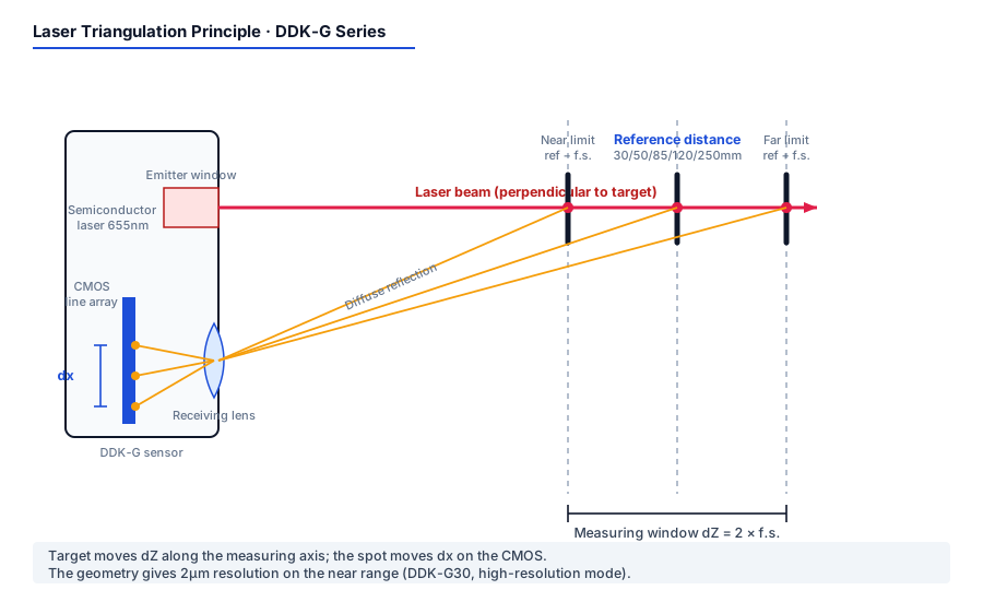
How Laser Triangulation Reads Microns
The DDK-G projects its 655 nm spot onto the target; the receiving lens images that spot onto a CMOS array at an angle. When the target moves toward or away from the sensor, the imaged spot slides along the CMOS — and that lateral shift converts geometrically into distance. The chip finds the spot centroid with sub-pixel interpolation, maps it through factory calibration, and updates one raw reading every sampling cycle (500 µs; 750 µs on the 250 mm grade), averaged 1, 16 or 64 times depending on the response mode. Because a micron-scale target move produces a measurable pixel shift, the 30 mm grade resolves 2 µm without touching the part.
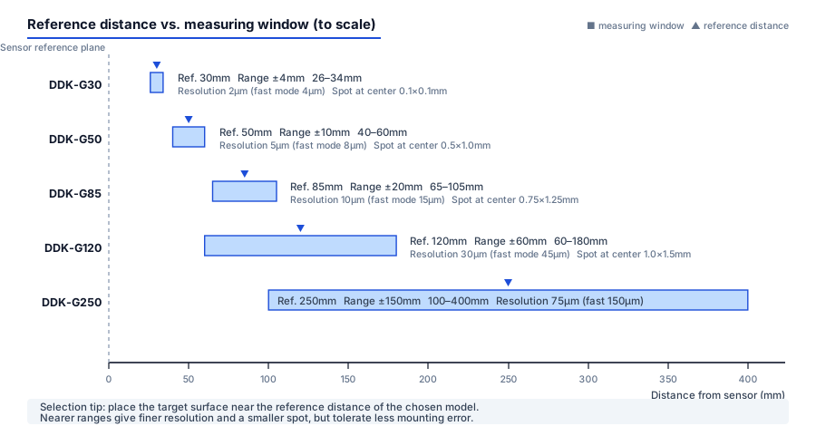
Specifications by Range Grade (Factory Datasheet)
| Item | DDK-G30 | DDK-G50 | DDK-G85 | DDK-G120 | DDK-G250 |
|---|---|---|---|---|---|
| Models | DDK-G30N(P)M / -485 | DDK-G50N(P)M / -485 | DDK-G85N(P)M / -485 | DDK-G120N(P)M / -485 | DDK-G250N(P)M / -485 |
| Reference distance | 30 mm | 50 mm | 85 mm | 120 mm | 250 mm |
| Measuring range | ±4 mm | ±10 mm | ±20 mm | ±60 mm | ±150 mm |
| Measuring window | 26–34 mm | 40–60 mm | 65–105 mm | 60–180 mm | 100–400 mm |
| Resolution (high-res) | 2 µm | 5 µm | 10 µm | 30 µm | 75 µm |
| Resolution (fast) | 4 µm | 8 µm | 15 µm | 45 µm | 150 µm |
| Linearity | ±0.1% F.S. (F.S. = 8 mm) | ±0.1% F.S. (F.S. = 20 mm) | ±0.1% F.S. (F.S. = 40 mm) | ±0.1% F.S. (F.S. = 120 mm) | ±0.3% F.S. (F.S. = 300 mm) |
| Spot size (centre) | 0.1 × 0.1 mm | 0.5 × 1.0 mm | 0.75 × 1.25 mm | 1.0 × 1.5 mm | 1.75 × 3.5 mm |
| Spot size (near / far end) | 0.15 × 0.15 mm both | 0.6 × 1.2 / 0.4 × 0.9 mm | 0.9 × 1.5 / 0.6 × 1.0 mm | 1.2 × 1.8 / 0.5 × 0.8 mm | 1.5 × 2.5 / 2.0 × 4.5 mm |
| Response time — fast | max 2 ms (1 sample avg. + sensitivity switch max 1 ms) | max 2.5 ms | |||
| Response time — standard | max 11.5 ms (16 samples, 8.5 ms + max 3 ms) | max 15.5 ms | |||
| Response time — high-res | max 36.5 ms (64 samples, 32.5 ms + max 4 ms) | max 48.5 ms | |||
| Sampling cycle | 500 µs (factory setting) | 750 µs | |||
Spot size defined at 1/e² (13.5%) of centre intensity — objects of higher reflectance adjacent to the spot can cause false readings outside the defined spot area. Rated under factory test conditions: 23 °C, DC24 V, high-resolution mode, target at range centre, 50 × 50 mm white ceramic.
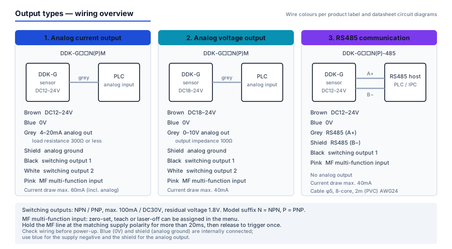
Output Types & Wiring
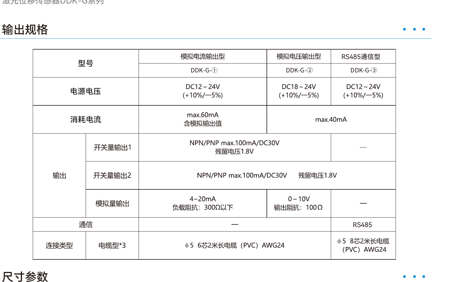
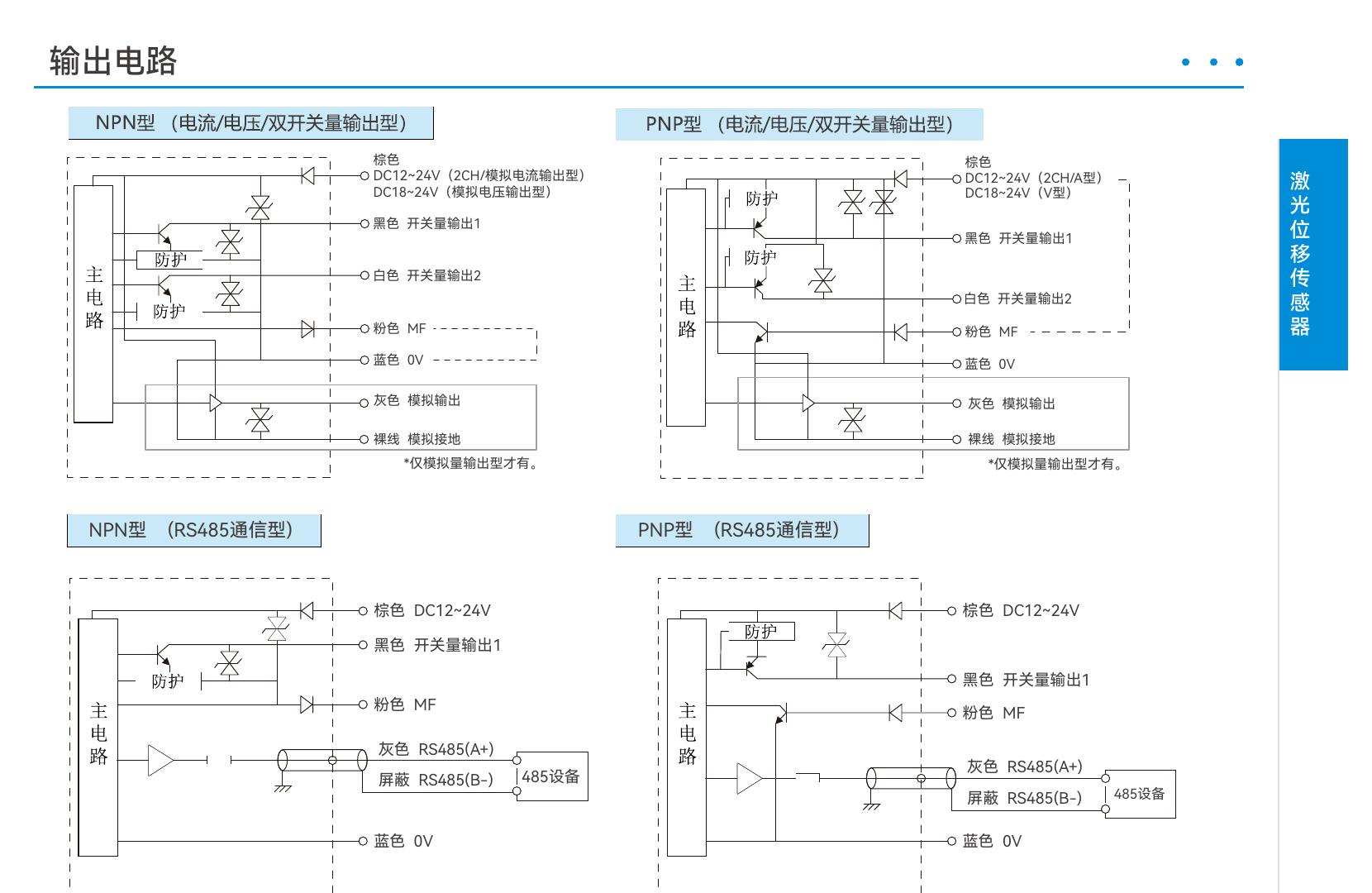
| Item | Analog current type (…N/PM) | Analog voltage type (…N/PM) | RS485 type (…N/P-485) |
|---|---|---|---|
| Supply voltage | DC12–24 V (+10%/−5%) | DC18–24 V (+10%/−5%) | DC12–24 V (+10%/−5%) |
| Current consumption | max 60 mA (incl. analog out) | max 40 mA | max 40 mA |
| Measurement output | 4–20 mA, load ≤300 Ω | 0–10 V, impedance 100 Ω | RS485 (grey = A+, shield = B−) |
| Switching outputs | 2 × NPN/PNP, max 100 mA / DC30 V, residual 1.8 V | same | 1 × NPN/PNP (per circuit diagram — confirm with factory) |
| Cable | φ5, 6-core, 2 m PVC, AWG24 | φ5, 6-core, 2 m PVC, AWG24 | φ5, 8-core, 2 m PVC, AWG24 |
Wire Colours
| Colour | Function |
|---|---|
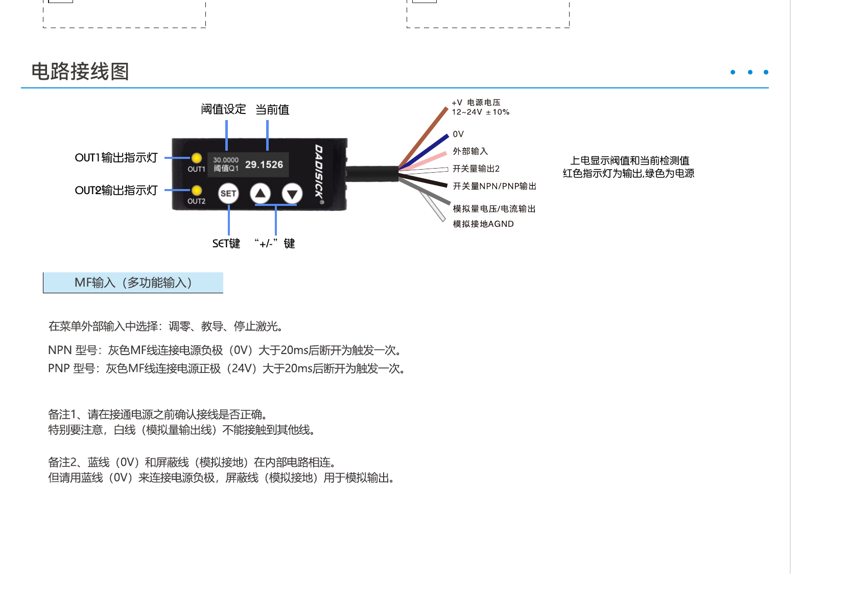
| Brown | DC supply + |
| Blue | 0 V |
| Black | Switching output 1 (NPN or PNP per model) |
| White | Switching output 2 (analog types) |
| Pink | MF multifunction input — zero-set / teach / laser-off (menu-selectable); pulse >20 ms to 0 V (NPN) or +24 V (PNP) |
| Grey | Analog output 4-20 mA / 0-10 V — or RS485 A+ on -485 models |
| Shield | Analog ground — or RS485 B− on -485 models |
Blue (0 V) and the shield (analog ground) are internally connected — wire the supply negative to blue and use the shield for the analog return. Keep the analog output line clear of other conductors, and verify all wiring before power-up. For switching-output polarity fundamentals see the PNP vs NPN wiring guide.
Electrical & Environmental (All Grades)
| Light source | Red semiconductor laser, 655 nm, max output 1 mW |
|---|---|
| Laser class | Class 2 (IEC/JIS) · Class II (FDA) |
| Temperature drift | ±0.08% F.S./°C |
| Display & keys | OLED (threshold Q1 + live value), SET + ▲▼ keys, OUT1/OUT2 orange indicators |
| MF multifunction input | Zero-set, teach, laser-off via menu; pink wire, pulse >20 ms |
| Protection circuits | Reverse-connection protection, overcurrent protection |
| Protection rating | IP64 |
| Ambient temperature / humidity | Operating −10 to +45 °C (no freezing), 35–85% RH · storage −20 to +60 °C, 35–95% RH |
| Ambient illuminance | Sunlight ≤10,000 lx · incandescent ≤3,000 lx |
| Vibration / shock | 10–55 Hz, 1.5 mm double amplitude, 2 h per axis · approx. 50 G (500 m/s²), 3 times per axis |
| Warm-up | Internal circuit stable ≈1.5 s; full warm-up max 15 min |
| Housing / lens | Aluminum alloy / PMMA |
| Dimensions | 50 (W) × 60 (H) × 20.4 (D) mm · 2 × φ4.5 mounting holes |
| Weight | 65 g cable type (excl. cable) · 90 g connector type |
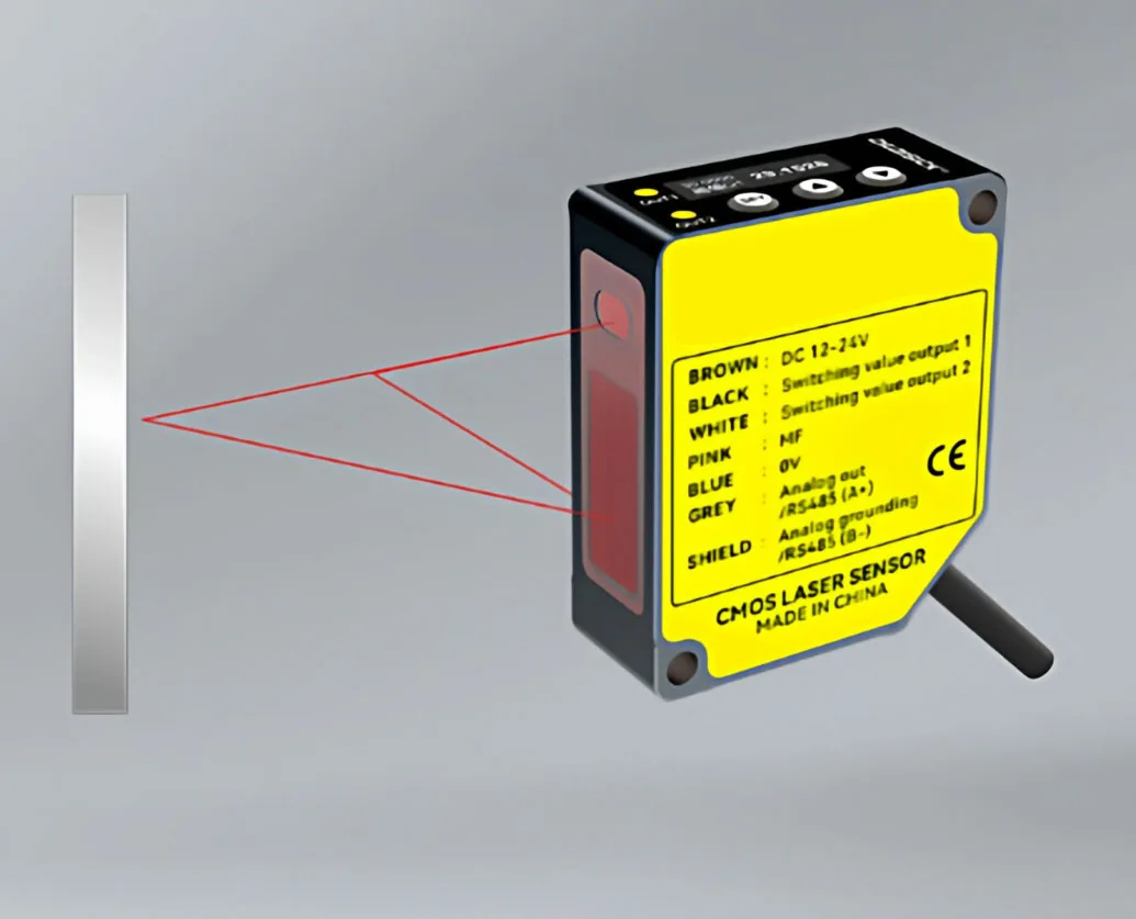
Dimensions & Feature Summary
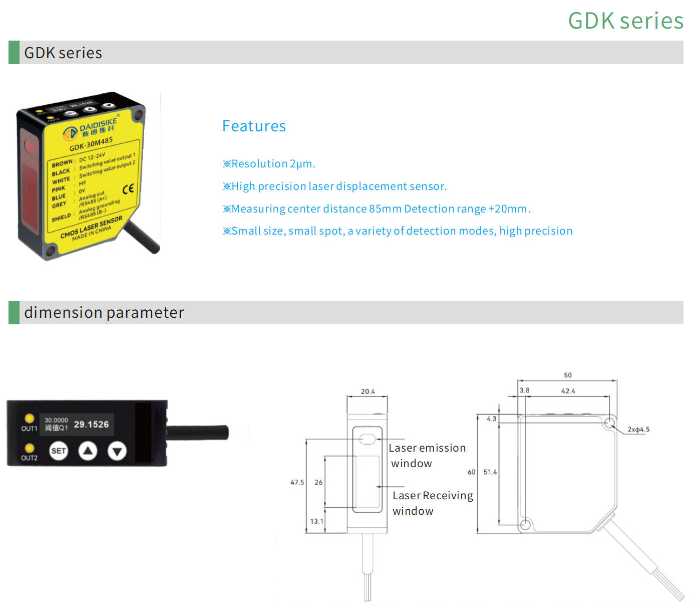
Product Views
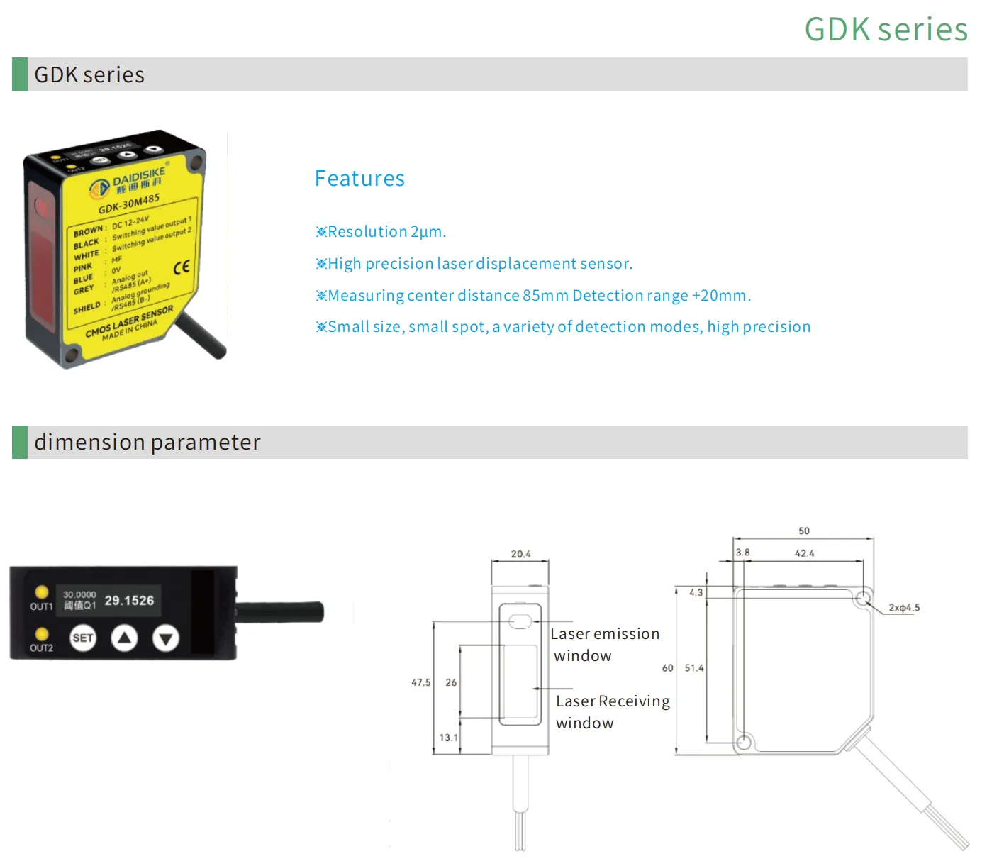

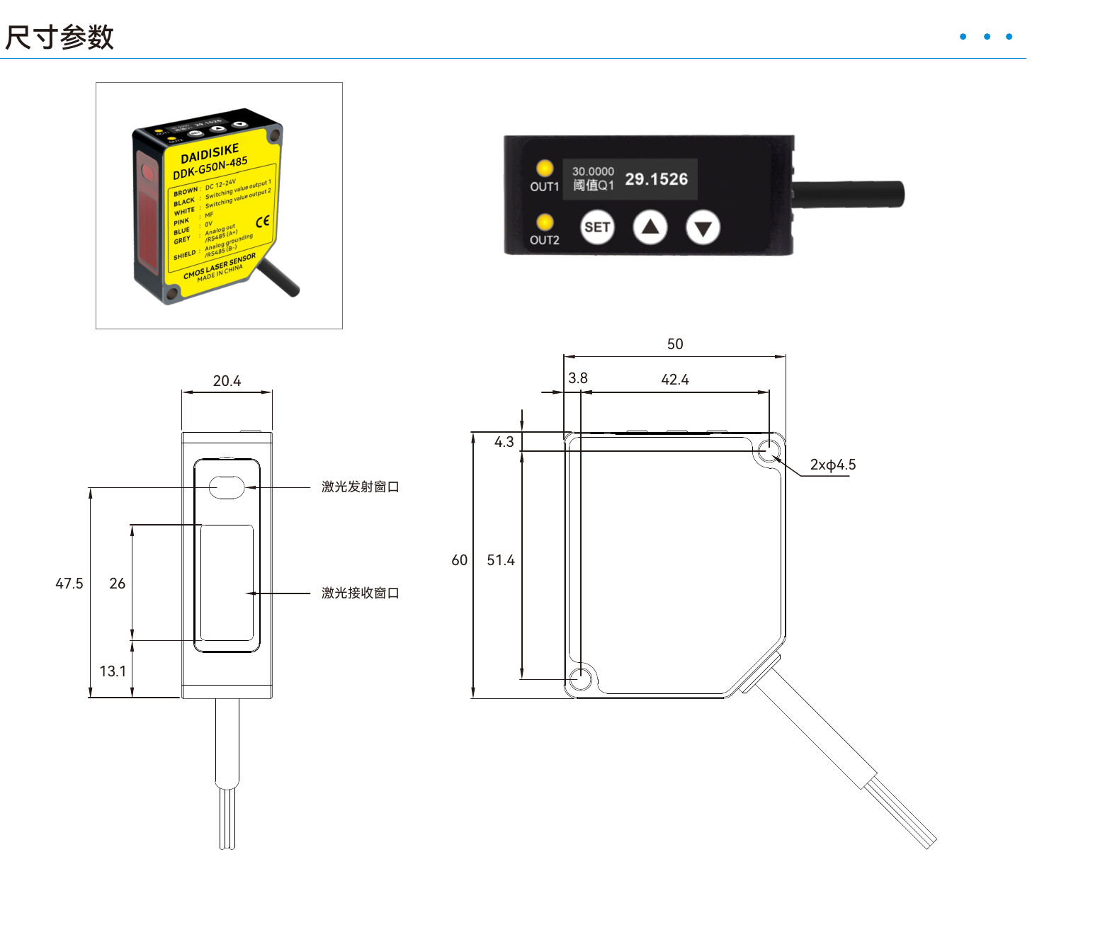
Six Applications — and Which Grade to Specify
- Lithium battery electrode coating / calendering thickness. Two opposed DDK-G30 units in a C-frame measure thickness differentially; 2 µm resolution tracks areal-density drift. High-resolution mode for stability, 4-20 mA over long runs, switching outputs as over/under alarms.
- 3C precision assembly float-height checks. Mid-frame bonding, display lamination, connector pin height: the G30's 0.1 × 0.1 mm spot lands on narrow bezels, and 2 µm resolves tens-of-microns lift. Standard mode for tight takt; RS485 streams values for SPC logging.
- Automotive in-line dimensioning. Brake-disc thickness, gear end-face runout, springback — DDK-G50 or G85 by part size. Fast mode (max 2 ms) keeps up with rotation; 0-10 V feeds the PLC, which computes peak-to-peak and the verdict.
- Steel plate / profile thickness and flatness. Long travel and distant mounting favour G120 or G250 — noting the G250's larger spot and ±0.3% F.S. linearity suit large flat surfaces, and red-hot stock radiating into the 655 nm band needs separate evaluation.
- Woodworking / building-board inspection. Good diffuse surfaces, heavy dust: G85/G120 for clearance, standard mode, 4-20 mA for long shop-floor runs, and an air-purge curtain where dust concentrates (IP64 is splash/dust-protected, not washdown-rated).
- Robot and line positioning feedback. Hopper level, stack height, roll diameter — large scatter favours G120 (±60 mm) or G250 (±150 mm). RS485 skips the A/D stage, switching outputs act as in-position flags, and MF-as-zero-set gives one-touch reset at changeover.
DDK-G vs Our Other Displacement & Distance Series
| Series | Positioning | Pick it when… |
|---|---|---|
| DDK-G (this page) | Fine-resolution triangulation, 30–250 mm, 2–75 µm, IP64 | You need micron-class reading at short range, or the 85/120/250 mm intermediate grades other series skip. |
| DK-G Series485 | Triangulation, 30–400 mm centres, IP60. Repeatability: 10 / 30 / 70 / 200 µm on the 30 / 50 / 100 / 200 mm grades; confirm the distance-dependent 400 mm grade separately. | You need the 400 mm centre distance or the DK-G's documented repeatability figures. |
| LK-F CMOS Series | CMOS triangulation, 30–400 mm, IP67 housing | Washdown or dusty conditions demand the IP67 body. |
| DSK-CG | Long-range distance measurement, 1–80 m, mm-class | The job is metre-range ranging (cranes, AGV, racks), not micron displacement. |
| DDA-Y / DDB-Y · DDK | Industrial laser distance sensor families | Alternative long-range ranging platforms — compare interfaces and range on their pages. |
DDK-G is a measurement component, not an IEC 61496 certified safety device — never use it as the sole protection for personnel. Repeatability data has not been published; for tolerance-critical acceptance criteria request test data from the factory first.
Browse the laser switching and non-contact measurement range for related optical methods. Where touching the workpiece is acceptable, compare contact-probe displacement sensors as a separate measurement method.
Downloads
PDFDDK-G Laser Displacement Sensor — English DatasheetAll 20 model codes, per-grade specification tables, the three output versions with wire colours and MF input, environmental ratings, target-surface guidance and factory test conditions.
Frequently Asked Questions
Is DDK-G the same product as the GDK series?
Yes. DDK-G is the factory's official model code printed on the datasheet and nameplate (e.g. DDK-G50N-485); some earlier catalog pages, including an older version of this one, listed the same sensor as "GDK". Order codes read DDK-G + reference distance (30/50/85/120/250) + N or P (NPN/PNP) + M (analog) or -485 (RS485) — 20 standard models in all.
What resolution and linearity does the DDK-G series achieve?
Resolution runs from 2 µm at the 30 mm reference distance to 75 µm at 250 mm in high-resolution mode (4-150 µm in fast mode). Linearity is ±0.1% of full scale on the 30/50/85/120 mm grades and ±0.3% F.S. on the 250 mm grade — full scale being the grade's total span (8 mm for the 30 mm grade, so about ±8 µm). Resolution, linearity and repeatability are different quantities; ask us for the right one for your tolerance study.
What laser does the DDK-G use, and is it safe to work around?
A 655 nm red semiconductor laser with 1 mW maximum output — Class 2 under IEC/JIS and Class II under FDA classification. Class 2 visible lasers are considered safe for momentary exposure because of the blink reflex, but the beam should never be viewed intentionally; follow your plant's laser handling rules.
How fast does the DDK-G respond?
Three selectable modes: fast (1 averaging sample) responds within max. 2 ms, standard (16 samples) within max. 11.5 ms, and high-resolution (64 samples) within max. 36.5 ms — the 250 mm grade reads 2.5/15.5/48.5 ms. The factory sampling cycle is 500 µs (750 µs for the 250 mm grade). Pick fast mode for moving targets and high-resolution mode for the finest reading on static targets.
Which output types are available, and what do the wires mean?
Three electrical versions: 4-20 mA current output (load ≤300 Ω, supply DC12-24 V), 0-10 V voltage output (impedance 100 Ω, supply DC18-24 V), or RS485 communication (DC12-24 V). Wire colours: brown +V, blue 0 V, black switching output 1, white switching output 2 (analog types), pink MF multifunction input, grey analog output — or RS485 A+ on -485 models, with the shield as analog ground or RS485 B−. Blue and shield are internally connected: use blue for supply negative and the shield for the analog return. Note the RS485 version's circuit diagram shows one switching output only — confirm with the factory if you need two.
What does the MF (multifunction) input do?
The pink MF wire is menu-assignable to zero-set, teach, or laser-off. To trigger once on an NPN model, connect MF to 0 V for more than 20 ms and release; on a PNP model, connect it to +24 V for more than 20 ms and release. Configured as zero-set it gives one-touch re-referencing after a product changeover — no panel access needed.
Which target surfaces are difficult for a triangulation sensor?
Mirror-polished metal reflects specularly away from (or too strongly into) the receiver — tilt the sensor off the specular angle and verify by trial. Transparent targets return a weak front-surface echo plus a rear-surface echo and read unstable; sample-test first. Deep matte black shrinks the signal margin, favouring a nearer-range grade. Red-hot workpieces radiate into the 655 nm band. Also keep shinier objects away from the spot's immediate surroundings: the spot is defined at 1/e² intensity and stray light outside it can cause false readings.
What should export buyers confirm before ordering?
Confirm the grade (30/50/85/120/250), output version (M analog — state 4-20 mA or 0-10 V — or -485), NPN or PNP, and cable termination (φ5 6-core 2 m PVC for analog, 8-core for RS485; a 90 g connector version is also listed). RS485 protocol details beyond the physical layer and repeatability data are not printed in the datasheet — request them from the factory. Rated figures assume the factory test conditions: 23 °C, DC24 V, high-resolution mode, white ceramic target at range centre.
Specs reviewed by Engineer Cai, Senior Application Engineer. See certificates.