中文官网

NON-CONTACT INDUSTRIAL MEASUREMENT

DDA-Y / DDB-Y Series
Industrial Laser Distance Sensor

Measure position and distance with a visible red laser, an IP67 metal housing and on-device setup. Choose a range up to 100 meters, use RS485 / RS232 and two switch outputs, or select DDB-Y when your controller needs analog feedback.

DAIDISIKE Laser Distance Sensor

DDA-Y / DDB-Y · 128 × 32 display · Four-button setup

01 / SELECT YOUR SERIES

Choose DDA-Y or DDB-Y

Start with the signal your controller needs, then choose the measuring range. For a different sensing task, use our laser sensor selection guide to compare distance, displacement and switching options.

DIGITAL & SWITCHING

DDA-Y Series

For applications that use serial distance data or switching thresholds without a voltage/current distance signal.

  • RS232 / RS485, selectable on the sensor
  • Two transistor switching outputs
  • Five range options from 10 m to 100 m maximum
  • No analog voltage or current output
WITH ANALOG FEEDBACK

DDB-Y Series

For a controller or analog input module that needs a continuous voltage or current signal representing distance.

  • RS232 / RS485 and two switch outputs
  • Voltage: 0–5 V or 0–10 V
  • Current: 4–20 mA, 0–20 mA or 0–24 mA
  • Select current or voltage; not both simultaneously
Order by the complete model and required output. The supplied operating manual describes NPN sinking switch outputs. Confirm the delivered wiring and output version; do not assume a PNP version or interchangeability with an existing sensor.

Model and Range Selection

Both series have a stated minimum distance of 0.2 m. Select the maximum range for your actual target and installation conditions.

Swipe the table sideways to see every model column →

Measuring rangeWithout analog outputWith analog output
0.2–10 mDDA-Y10DDB-Y10
0.2–20 mDDA-Y20DDB-Y20
0.2–30 mDDA-Y30DDB-Y30
0.2–50 mDDA-Y50DDB-Y50
0.2–100 mDDA-Y100DDB-Y100

Model names identify the nominal range, not a promise that every surface or environment can be measured at that maximum distance. The series-level CAD files are not ten individually verified model drawings.

02 / PERFORMANCE & CONDITIONS

Key Parameters and Detailed Specifications

Read the measurement values together with the conditions below. The visible laser assists alignment; the sensor measures the return from the target surface without contact.

Measuring Range

0.2 – 100 m (model dependent)

Measurement Error

±(2 mm + 0.01% of distance), at speed grade 1

Laser Class

Class II, 660 ±15 nm, ≤1 mW

Ingress Protection

IP67 · die-cast zinc alloy housing

Measurement Speed

1–40 Hz in the specification table; see speed-setting note below

Output Types

Two switch outputs + RS485/RS232; analog output on DDB-Y

Swipe the table sideways to compare all specifications →

ParameterDDA-Y SeriesDDB-Y Series
Measurement Performance
ModelsDDA-Y10 / DDA-Y20 / DDA-Y30 / DDA-Y50 / DDA-Y100DDB-Y10 / DDB-Y20 / DDB-Y30 / DDB-Y50 / DDB-Y100
Range0.2–10 / 20 / 30 / 50 / 100 m, by modelSame five range options
Measurement error±(2 mm + 0.01% of actual distance), at speed grade 1; target and environmental conditions apply
Resolution1 mm
Measurement frequency1–40 Hz in the source specification table; the setup text describes approximately 10–40 Hz across five speed grades. Confirm the required setting before integration.
LaserClass II; 660 ±15 nm; ≤1 mW
Spot diameterØ6 mm at 1 m · Ø8 mm at 10 m · Ø12 mm at 20 m · Ø16 mm at 30 m
Electrical Characteristics
Power SupplyDC 15–30 V
Power Consumption< 3.0 W
Switch OutputsTwo transistor outputs; supplied manual describes NPN sinking outputs. Do not exceed DC 36 V / 0.5 A; the wiring note specifies current below 500 mA. Confirm the exact supplied version.
Analog OutputNoneSelectable 0–5 V / 0–10 V / 4–20 mA / 0–20 mA / 0–24 mA; current and voltage are not simultaneous
Analog output errorNot applicableVoltage: 0.2% + 0.5 mV; current: 0.2% + 0.005 mA (source brochure values)
Communication & Environment
InterfaceRS232 / RS485 (menu-selectable)
Serial integrationCommand frames and registers are provided in the operating reference. Confirm protocol, register interpretation and PLC settings for the delivered firmware; not a universal plug-and-play compatibility claim.
Display & controls128 × 32 dot-matrix display with SET, ESC, up and down buttons
Operating Temp.–10°C to +50°C
Storage–20°C to +60°C; 20–85% RH
Protection RatingIP67
Housing MaterialDie-cast zinc alloy
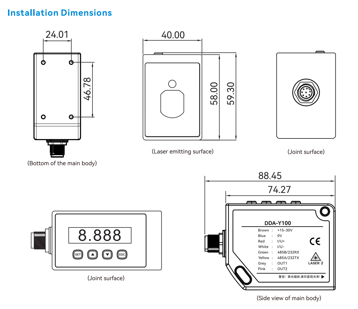
Overall dimensions88.45 × 40 × 59.3 mm, including connector base; check the mounting-version note before making a bracket

Accuracy is conditional

The quoted error applies at speed grade 1, with distance expressed in consistent units. Strong sunlight, a difficult target or a large temperature change can increase error. A suitable reflector may help, but test the actual arrangement.

Resolution is not accuracy

The stated 1 mm resolution is not a ±1 mm accuracy claim. Choose the sensor using the complete measurement-error specification and the conditions of the application, not the display increment alone.

Confirm the speed setting

The source table states 1–40 Hz. Its setup text gives approximately 10 Hz at grade 1 and approximately 40 Hz at grade 5. These source descriptions are not identical; confirm your required update rate before commissioning.

Source basis: the English datasheet and the supplied operating manual/technical brochure, with DAIDISIKE branding and the supplier-confirmed mounting dimension. The reference translations identify remaining source discrepancies rather than silently resolving them. Preview all three PDFs below.

03 / MECHANICAL DESIGN

Dimensions, Mounting and 3D CAD

Use the outline drawing for an initial layout, then confirm the controlled drawing for your ordered version before drilling, machining or selecting a bracket.

DDA-Y and DDB-Y mechanical dimension drawing showing the housing and connector base
Overall dimensions: 88.45 × 40 × 59.3 mm, including the connector base. Open the drawing for a closer view.
Confirmed mounting-hole spacing: 46.78 mm. The supplier confirmed this dimension for the current DDA-Y/DDB-Y version on 23 September 2026. The revised English documents use this confirmed value. Match the ordered hardware to its controlled drawing before making mounting parts; do not scale a screenshot or assume that the series-level CAD verifies every configuration.

Installation checks

  • Allow clearance for the connector and cable bend.
  • Keep the optical opening unobstructed and align it with the intended target.
  • Check the 0.2 m minimum measurement distance throughout the travel.
  • Use a stable fixture and verify the reference position after mounting.

Two series CAD entries

DDA-Y and DDB-Y STEP downloads are available below. The two supplied files contain identical geometry; the source CAD does not identify a range variant. They support layout review, not independent verification of all ordered configurations.

Open PDF & CAD downloads ↓

04 / CONTROLLER CONNECTION

Outputs and Wiring

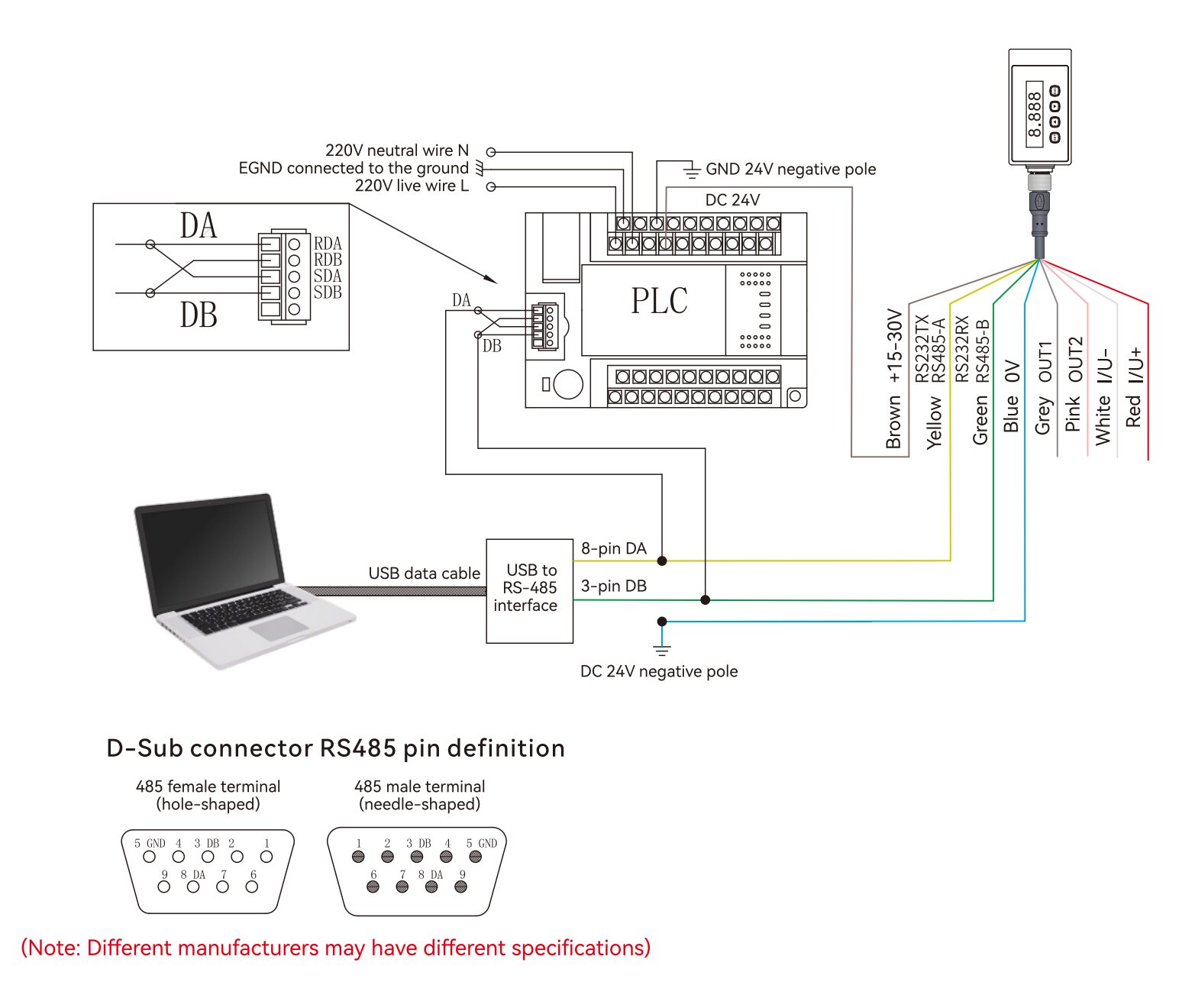
Check the delivered label, cable and operating manual with power disconnected. The table below is the sensor-side eight-pin assignment, not the pinout of a USB or D-Sub converter.

Swipe the table sideways to read all wiring details →

Sensor pinWire colorSignalFunction
1WhiteI/U−Analog return, DDB-Y only
2Brown+15–30 VDC power supply positive
3GreenRS232 RX / RS485 BCommunication, according to the selected interface
4YellowRS232 TX / RS485 ACommunication, according to the selected interface
5GreyOUT1Switching output 1
6PinkOUT2Switching output 2
7Blue0 VDC supply return
8RedI/U+Analog signal, DDB-Y only

The manual identifies the shield as earth grounding. I/U+ and I/U− apply to the analog-equipped DDB-Y version; their appearance in generic drawings does not add analog output to DDA-Y.

DDA-Y and DDB-Y wiring reference with power, communication, switching and analog signals
Existing wiring reference. Confirm connector orientation and version against the sensor label and the documents before connecting.

RS232 / RS485

Select the interface on the sensor and match the controller settings. The source gives 9600 baud, 8 data bits, 1 stop bit and no parity as the default; verify the current settings rather than assuming a used sensor is still at default.

For RS232, cross-connect TX and RX with the correct signal reference. For RS485, follow the A/B labeling and bus guidance for your controller. The manual supports station addresses 1–64; the source’s converter pin 8 is not sensor pin 8.

Two switching outputs

OUT1 and OUT2 have configurable threshold and output settings. The source describes NPN sinking behavior. Verify the controller input type and required switching logic before applying it to the machine.

The source limit is DC 36 V / 0.5 A, with a wiring note specifying current below 500 mA. For background only, see NPN sinking versus PNP sourcing explained; that guide’s 3/4-wire examples do not replace this eight-pin table.

DDB-Y analog output

Select one current or voltage mode and match it to the receiving input. Set the lower and upper distance limits for the intended signal span. Do not configure a voltage signal as though it were a current loop.

The translated manual flags inconsistent numbers in one current-output example. Check the scaling using known distances and confirm the formula/settings for the supplied unit before relying on a displayed engineering value.

PLC / Modbus RTU integration: the operating reference includes serial frames and registers, but some register descriptions are inconsistent. Confirm the firmware, protocol, data interpretation and error handling with us before using the examples in a control program. A matching RS485 physical connection alone does not establish protocol compatibility.

05 / LOCAL CONFIGURATION

Display and Setup

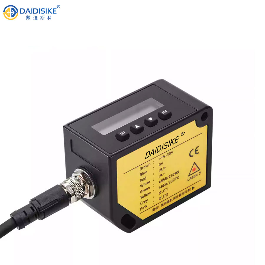
The 128 × 32 dot-matrix display shows the station number, measured distance and unit. Four buttons support local configuration without connecting a computer.

DDA-Y/DDB-Y housing with on-device distance display and setup buttons

SET · ESC · ▲ · ▼

Hold SET to enter settings; use SET to confirm and ESC to return. The arrow buttons select or adjust the value. See the operating manual for the complete button and menu instructions.

Watch the existing product demo ↗
  1. Confirm the hardware

    Record the complete model, range, wiring label and firmware information. Check whether analog output is required and present.

  2. Establish a reference target

    Mount securely, align the beam and compare the displayed distance with a known position under the intended lighting conditions.

  3. Set communication and outputs

    Choose the serial interface, station and format; then configure the required switch thresholds or DDB-Y analog mode and span.

  4. Validate before production

    Test the relevant distances, output transitions, signal scaling and communication errors with the machine in a safe commissioning state. Record the verified settings.

The display backlight can time out after 30 minutes or be set to remain on. Setup screenshots in the reference manual show example values; they are not necessarily your delivered configuration.

06 / APPLICATION FIT

Typical Applications — What to Check First

Position, displacement, level, thickness and distance are different measurement tasks. The right model depends on the target and measurement geometry, not only the maximum range printed in its name.

Swipe the table sideways to read each application check →

TaskPossible measurement arrangementConfirm before selecting
Machine or carriage positionMeasure the changing gap to a defined target along the laser axis.Confirm the full travel, minimum distance, target size and required update rate.
Material level or fill heightMeasure distance to a suitable material surface and relate it to a known reference height.Test the actual surface, dust, slope and return signal. Liquid and highly reflective targets require an application test.
Displacement or thickness checksObserve a change in distance relative to a stable reference.Check fixture stability and geometry. Thickness requires a defined reference arrangement; a single distance reading is not automatically a thickness result.
Long-span distance monitoringMonitor a suitable target within the selected model’s stated range.Check ambient light, temperature variation, alignment and reflector requirements on site. This is not a safety-rated protective sensor.
Measurement is not machine safeguarding. The Class II laser and IP67 housing do not establish a functional-safety performance level. Do not use this distance sensor as a substitute for a validated protective device or safety system.

07 / ENGINEERING RESOURCES

Three English PDFs, Each with Preview and Download

Use the English datasheet for the technical overview, the operating reference for menus, wiring and source protocol details, and the technical brochure reference for model tables and illustrated connections. All three use DAIDISIKE branding. Reference translations identify remaining source differences; confirm the relevant details before installation.

PDF & 3D CAD Downloads

Browse all downloads

DDA-Y / DDB-Y Laser Ranging Sensor - English Datasheet

English · 5.2 MB

DAIDISIKE English datasheet, retained at its original download address.

DDA-Y / DDB-Y Operating Manual - English Reference Translation

English · 1.8 MB

DAIDISIKE English operating reference with translated diagram labels and supplier-confirmed 46.78 mm mounting-hole spacing. Remaining source inconsistencies are flagged; confirm settings before commissioning.

DDA-Y / DDB-Y Technical Brochure - English Reference Translation

English · 1.4 MB

DAIDISIKE English technical brochure covering model selection, measurement conditions, dimensions and wiring, with the confirmed mounting-spacing note. Confirm the exact sensor and adapter pinouts before use.

3D CAD MODELS

Find the file for your exact model

Open the download center with the named series selected. Search your full model, check the file details and download the matching STEP file.

Confirm the document and CAD file match your exact ordered version before installation or mechanical design. Contact us if your model is not listed.

08 / QUICK ANSWERS

Frequently Asked Questions

What is the measuring range and accuracy of the DDA-Y / DDB-Y laser distance sensor?

The five model ranges are 0.2–10, 0.2–20, 0.2–30, 0.2–50 and 0.2–100 m. The source specifies ±(2 mm + 0.01% of actual distance) measurement error at speed grade 1 and 1 mm resolution. Resolution is not the same as accuracy. Target reflectivity, strong light and temperature changes can affect the result, so validate the intended position, level or thickness-measurement arrangement with the actual target.

What is the difference between the DDA-Y and DDB-Y models?

Both series offer the same five stated range options, two switching outputs, RS232/RS485 communication and IP67 housing. DDA-Y has no analog output. DDB-Y adds selectable 0–5 V, 0–10 V, 4–20 mA, 0–20 mA or 0–24 mA output. Current and voltage cannot be output simultaneously. The supplied operating manual describes NPN sinking switch outputs; confirm the output type on the ordered version rather than assuming PNP is available.

Does the sensor support Modbus RTU and how do I wire RS485 or RS232?

RS485 and RS232 are selectable in the on-device communication settings. The supplied manual includes command frames and a register table, but it contains register-description inconsistencies, so confirm Modbus RTU requirements, firmware and register interpretation before programming a PLC or SCADA system. Use the sensor’s eight-pin wire table on this page: green is RX/B and yellow is TX/A. The source supports station addresses 1–64 and networking of up to 64 instruments; the illustrated converter’s pin numbers are not the sensor’s connector pin numbers.

Is the DDA-Y / DDB-Y laser sensor safe and rated for harsh environments?

The specified laser is Class II, 660 ±15 nm and ≤1 mW. Do not stare into the beam. The zinc-alloy housing is rated IP67, with an operating range of –10°C to +50°C and storage range of –20°C to +60°C at 20–85% RH. IP67 is not a guarantee for every washdown, chemical or vibration condition. The source describes measurement stopping above 70°C body temperature and resuming below 70°C; this is not permission to operate above the stated ambient limit. No functional-safety rating is established by these documents.

Can this laser distance sensor replace an imported brand for industrial level or position measurement?

It may be considered for an alternative design after an engineering comparison, not as an automatic drop-in replacement. Compare range, target, measurement conditions, response setting, mounting drawing, connector wiring, output behavior and communication protocol against the existing unit. Send the exact existing model and application details so the differences can be checked before ordering.

Which PDF and CAD file should I use before installation?

The download area contains the English datasheet, an English operating-manual reference translation and an English technical-brochure reference translation. Each has separate preview and download links. The two supplied DDA-Y/DDB-Y STEP files have identical geometry and do not identify a range variant. The supplier confirmed 46.78 mm mounting-hole spacing for the current DDA-Y/DDB-Y version on 23 September 2026; confirm the ordered hardware and controlled drawing before drilling or machining.

Can I use the maximum measurement speed with the quoted accuracy?

Do not assume so. The quoted measurement-error specification is explicitly tied to speed grade 1. The specification table lists 1–40 Hz, while the operating text describes approximately 10 Hz at grade 1 and approximately 40 Hz at grade 5. Confirm the update rate and measurement error needed for your process using the delivered unit and actual target.

09 / ENGINEERING SUPPORT

Send the Details That Make Selection Easier

A model name alone is not enough to confirm fit. Share these six details so we can review the range, output and installation requirements together.

Contact an Engineer
  1. Distance: minimum, maximum and required measurement tolerance.
  2. Target: material, color, surface and usable target area.
  3. Movement: static or moving, speed and required update rate.
  4. Output: RS232/RS485, switching, voltage or current; controller model.
  5. Environment: indoor/outdoor, temperature, light, dust and moisture.
  6. Configuration: full model, existing sensor if replacing, connector and mounting space.

Specs reviewed by Engineer Cai, Senior Application Engineer. See company certificates. Product settings and source-document differences still require confirmation for the ordered version.

Share this pageEmailWhatsAppLinkedIn