
Proximity Sensor Wiring Guide: PNP vs NPN, 3-Wire vs 4-Wire (With Diagrams)
In industrial automation, proximity switches are essential sensors. They detect objects without physical contact and are widely used for counting and positioning. Ordinary proximity switches do not provide personnel protection. However, for many engineers, the confusion between PNP vs NPN and 3-wire vs 4-wire configurations can lead to equipment failure or even fried PLC modules.
This guide from FSDDSK covers the basic principles and the practical wiring methods, so you can connect each sensor type correctly the first time.
I. Understanding the Basics: PNP vs NPN
Before wiring, it is crucial to understand what is a proximity switch and how its output type interacts with your controller. The core difference lies in the Output Type.
1. Sourcing vs Sinking
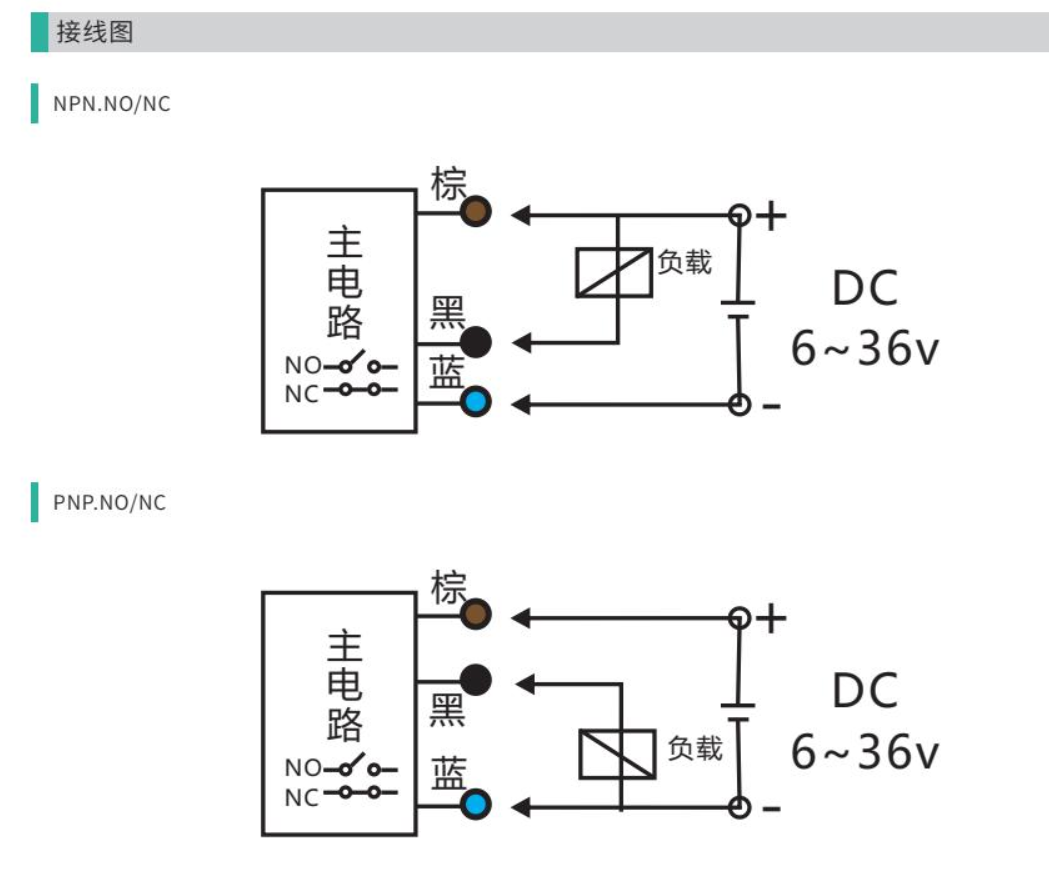
- NPN (Sinking Output): When triggered, the output (Black wire) connects to the Negative (Blue wire), outputting a Low Level signal. Current flows from the load into the sensor.
- PNP (Sourcing Output): When triggered, the output (Black wire) connects to the Positive (Brown wire), outputting a High Level signal. Current flows from the sensor into the load.
Pro Tip: Think of NPN as “Pulling Down” to 0V and PNP as “Pushing Up” to +24V.
2. Why two types?
Read the input-card circuit rather than infer it from the PLC brand. A PNP sourcing output feeds a sinking input referenced to 0 V; an NPN sinking output receives current from a sourcing input referenced to the positive supply. This matches OMRON’s load-placement diagrams.
II. 3-Wire Proximity Sensors: The Industry Standard
The 3-wire proximity sensors are the most common in the industry, consisting of two power lines and one signal line.
Standard Color Codes (International Standards):
- Brown (BN): Positive (+V, usually +24V DC)
- Blue (BU): Negative (0V / GND)
- Black (BK): Signal Output
III. 4-Wire Proximity Sensors: NO + NC Flexibility
Our high-performance 4-wire proximity sensors can provide a White (WH) complementary output on a specifically documented NO/NC model. The following roles are an example, not a universal four-wire pinout.
- Brown (BN): +V
- Blue (BU): 0V / GND
- Black (BK): Normally Open (NO) Output
- White (WH): Normally Closed (NC) Output
Example: documented complementary-output sensor
Brown → rated positive supply; blue → 0 V.
Black NO → compatible input A; white NC → separate compatible input B.
For PNP outputs use sinking inputs; for NPN use sourcing inputs. Insulate unused output wires individually. Do not connect white to blue or join the two outputs.
The four-wire example illustrates complementary NO/NC outputs. Other models may use the extra conductor for teach, enable or alarm. IO-Link communication uses the documented C/Q connection (commonly pin 4), not simply whichever wire is fourth; confirm the exact pinout and insulate unused conductors individually. The photoelectric sensor wiring guide shows the same sourcing/sinking circuit logic with a separate through-beam transmitter and receiver.
IV. Pre-Wiring Checklist: Avoid Frying Your Sensor
Before you power up, run through this checklist from our technical team:
- Voltage Check: Use the exact sensor’s supply rating, allowable ripple and polarity. Never connect to AC unless specified.
- Polarity: Verify Brown is + and Blue is −. Confirm the model pinout and protection before energising.
- PLC Compatibility: Ensure your PLC input matches the sensor (PNP sourcing output to sinking input; NPN sinking output to sourcing input).
- Load Current: Ensure the connected relay stays within the specified continuous and inrush output limits; a generic 200 mA value is not a design rating.
V. Common Troubleshooting
- Sensor LED is on, but no PLC signal: Check output logic, PLC common, supply and the input threshold. An LED alone does not identify the fault. Measure with the documented load connected and follow the machine’s electrical test procedure.
- Frequent false triggers: Check for metal interference or unstable power.
- Sensor burns out: Immediately check for reversed polarity or a short circuit.
Conclusion: Selecting the right proximity sensor wiring is crucial for system stability. For professional industrial sensors and technical support, visit www.fsddsk.com.