One mechanical platform, two sensing brains. The DAIDISIKE reflective area light grid family mounts on a single side — no opposite receiver, no beam alignment, wiring at one end only — and comes in two series that share every housing dimension, mounting hole and model tier. The DD diffuse-reflection type judges object presence from reflected light energy and reaches 2000 mm. The DDOF time-of-flight (TOF) type measures distance independently on every beam axis and triggers only inside a set distance window: up to 4000 mm with no blind zone, immune to background colour and target reflectivity, with one-key distance setting — that is its background suppression. Both give 4–50 even beams at a 40 mm pitch (detection heights 160–2000 mm), NPN + PNP outputs fitted simultaneously, and a 35 × 35 mm extruded body with LED indicators and a digital display.
Important: both series — DD and DDOF — are intended for area detection only and must not be used as a safety guarding device or for personnel protection.
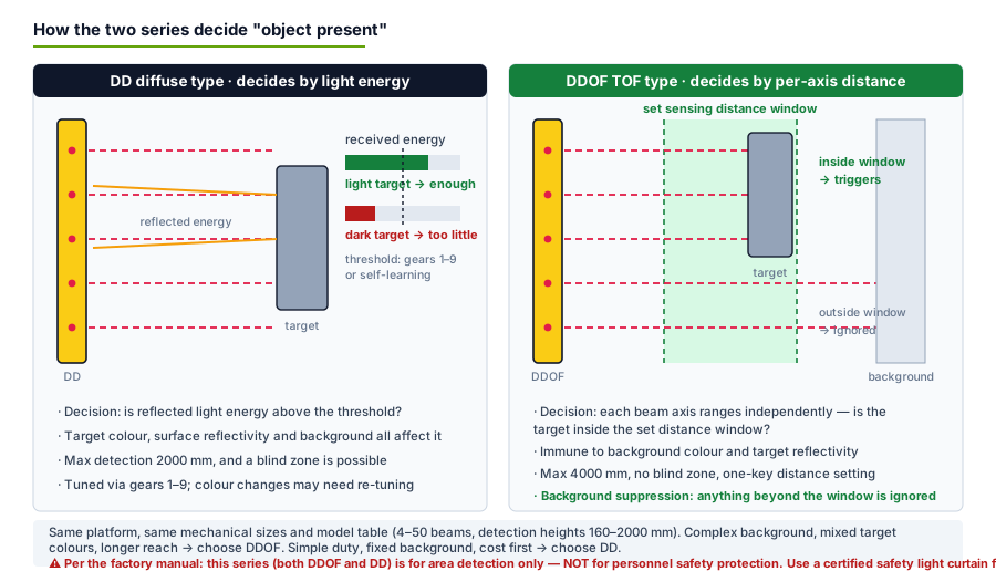
Figure 1: the decision each series makes. Left — the DD compares reflected energy against a threshold set by gears 1–9 or self-learning. Right — the DDOF ranges each axis and reports an object only inside the set window, which is why the background simply cannot false-trigger it.
An energy-based diffuse sensor can be fooled twice over: a dark, matt or angled surface returns too little light and gets missed, while a bright background returns too much and gets "seen". That is why the DD wants a stable background and a re-tune when the product colour changes. The DDOF asks a different question on each axis — not how much light came back but how far away is whatever came back — and compares that distance against the window you set with one key press. Anything beyond the window, including the wall itself, is ignored. That single change of question is what buys the 4000 mm reach, the absence of a blind zone, and the immunity to target colour and background reflectivity.
Function
DD — diffuse reflective type
DDOF — TOF (time-of-flight) type
Detection method
Judges presence from reflected light energy intensity
Each beam axis measures distance independently; triggers inside the set window
Maximum detection distance
Up to 2000 mm
Up to 4000 mm
Blind zone
May have a blind zone
No blind zone
Effect of background colour / target reflectivity
Affected; a stable background is required
Not affected; distance attenuation is small
Distance setting
Gears 1–9, plus self-learning at gear 0
One-key distance setting
Output
NPN + PNP fitted, NO/NC selectable
NPN + PNP fitted, NO/NC selectable
Beam count
4–50 even (customizable)
4–50 even (customizable)
Typical pick
Fixed background, uniform product, cost first
Moving/complex background, mixed colours, >2000 mm, no-blind-zone required
Model Selection Table — All 24 Tiers, Both Series
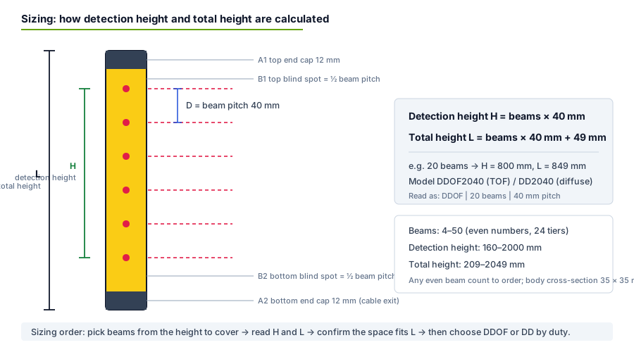
Model numbers read series + beam count + pitch: DDOF2040 is the TOF type with 20 beams at 40 mm pitch. Two formulas generate the whole family — detection height H = beams × 40 mm, total housing height L = H + 49 mm (12 mm caps top and bottom plus the mounting allowance). Pick the tier whose H covers the zone you need to monitor, confirm the space fits L, then choose DD or DDOF by duty. Any even beam count outside the table is built to order.
Beams
DDOF model (TOF)
DD model (diffuse)
Detection height H (mm)
Total height L (mm)
4
DDOF0440
DD0440
160
209
6
DDOF0640
DD0640
240
289
8
DDOF0840
DD0840
320
369
10
DDOF1040
DD1040
400
449
12
DDOF1240
DD1240
480
529
14
DDOF1440
DD1440
560
609
16
DDOF1640
DD1640
640
689
18
DDOF1840
DD1840
720
769
20
DDOF2040
DD2040
800
849
22
DDOF2240
DD2240
880
929
24
DDOF2440
DD2440
960
1009
26
DDOF2640
DD2640
1040
1089
28
DDOF2840
DD2840
1120
1169
30
DDOF3040
DD3040
1200
1249
32
DDOF3240
DD3240
1280
1329
34
DDOF3440
DD3440
1360
1409
36
DDOF3640
DD3640
1440
1489
38
DDOF3840
DD3840
1520
1569
40
DDOF4040
DD4040
1600
1649
42
DDOF4240
DD4240
1680
1729
44
DDOF4440
DD4440
1760
1809
46
DDOF4640
DD4640
1840
1889
48
DDOF4840
DD4840
1920
1969
50
DDOF5040
DD5040
2000
2049
Figure 2: the sizing algorithm. Note the two structural dead points — B1 = ½ pitch (20 mm) at the top, B2 = ½ pitch + 25 mm (45 mm) at the bottom cable-exit end. Orient the cable end away from the edge where detection matters most.
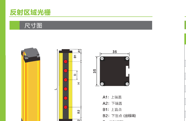
Figure 3 (factory drawing): 35 × 35 mm cross-section with T-slot mounting channel.
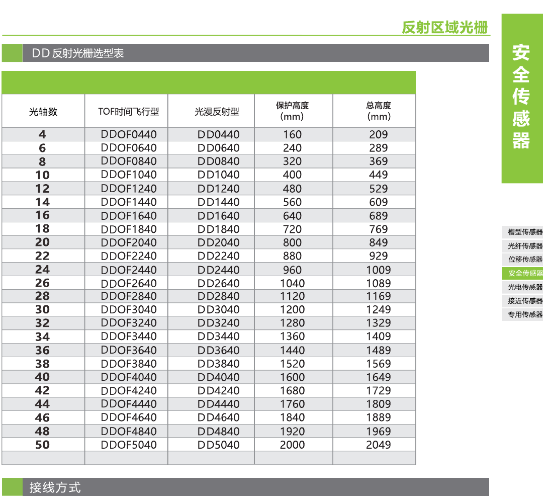
Figure 4 (original factory table, Chinese): the same 24 tiers transcribed in English above.
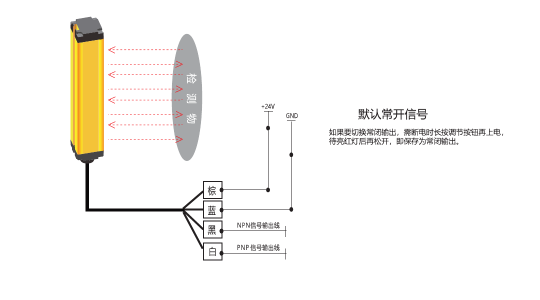
Wiring: Four Wires, Both Output Types Fitted
Every unit ships with both output transistors, so one model covers NPN and PNP installations — connect the wire that matches your PLC input card and insulate the other.
Switching to normally-closed output: with power off, press and hold the adjustment button; keep holding while powering on; release once the red LED lights — the NC setting is saved. If the output participates in any stop or interlock logic, NC is the sensible choice: a cut cable then reads as "object present" instead of silence. (And if that stop logic protects a person, stop — this series is the wrong product; see the notice below.) The factory sheet does not print the output load rating; for polarity fundamentals see our NPN vs PNP wiring guide.
DD Gears 1–9, Self-Learning, and the DDOF One-Key Setting
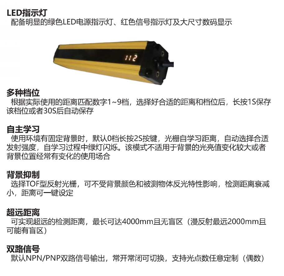
Gears (DD): match gear 1–9 to the actual working distance — higher gears raise emission intensity and reach. Long-press 1 s to save the gear, or it auto-saves after 30 s. The manual publishes no gear-to-millimetre table; tune against the real target and background.
Self-learning (DD): at the default gear 0, long-press 2 s where the background is fixed. The grid learns the distance and selects a suitable emission intensity itself; the green LED flashes while learning. Not suitable where background brightness varies greatly or the background position changes frequently — automatic doors and lifting platforms are the classic failure cases.
One-key distance (DDOF): set the sensing window with a single key press. Because judgment is by distance, changing product colour or film does not require re-tuning — the window stays valid.
Indicators (both): green LED = power, red LED = signal, large digital display shows the active gear/status.
Figure 6 (original factory chart, Chinese): the six capabilities described above.
Application limits / compliance notice. Per the factory manual, this reflective light grid series — both the DD diffuse type and the DDOF TOF type — is intended for area detection only and must not be used for safety protection purposes. Neither series is certified to IEC 61496, EN ISO 13849-1 (PL) or IEC 62061 (SIL). Do not use either as a safety guarding device, for personnel protection, or as the sole means of stopping a machine to protect a person — the DDOF's better detection performance does not change this. The page URL retains the historical wording "safety light curtains"; the family is a detection light grid. Where a workstation needs actual personnel protection, specify a certified through-beam safety light curtain — see the DQT4 Type 4 family or ask us with your PLr and opening size.
Six Application Scenarios — and Which Series to Pick
Conveyor package & rack-slot detection. Side-mounted to detect package arrival or slot occupancy. DD suffices when cargo is uniform cartons against a fixed baffle; go DDOF when black totes, stretch-wrapped pallets and light cartons mix on one line, or the aisle span exceeds 2000 mm.
AGV and forklift passageways. One column at the doorway detects passage. Clear widths of 2–4 m and wildly varying surfaces (black tyres, stretch film, metal pallets) make DDOF the default — 4000 mm, no blind zone, colour-independent. DD only for narrow passages with a fixed wall and consistent vehicles.
Automatic doors and equipment openings. A moving door shifts the background constantly — explicitly unsuitable for DD self-learning. Choose DDOF and use the distance window to exclude the moving door entirely.
Palletizing and robot cells. Area occupancy and stack-level detection; typical heights 800–1600 mm map to 20–40 beams. Moving pallets and mixed loads favour DDOF. Reminder: if the requirement is a person-entry stop function, that is a certified safety curtain's job, not this series'.
Packaging machine in/outfeed. Material arrival and stack height within 2000 mm against a fixed frame: DD's gears do it for less money. Transparent or metallized film whose reflectivity jumps → DDOF, or test with real samples first.
Roller shutters and lifting platforms. A platform that rises and falls is the textbook "background position keeps changing" case: DDOF with a locked distance band. Personnel protection at the same spot needs a separate certified curtain.
Compiled in English from the 2026-08 factory manual. Values not printed by the factory (response time, IP rating, electrical tolerances) are marked "confirm with factory" rather than guessed.
Frequently Asked Questions
Can the DD or DDOF series be used for personnel safety protection?
No — neither series. The factory manual states this reflective light grid series is recommended for area detection only and must not be used for safety protection purposes, and that covers both the DD diffuse type and the DDOF TOF type. Neither is certified to IEC 61496, EN ISO 13849-1 or IEC 62061. Do not connect either series into a stop circuit whose job is to protect a person. The product name and URL of this page keep the historical wording "safety light curtains", but this family is a detection light grid, not a certified safety component. For personnel protection specify a certified through-beam safety light curtain such as the DQT4 instead.
What is the difference between the DD and DDOF series?
Same housing, same 24-model table, different sensing brain. The DD diffuse-reflection type judges object presence from the intensity of reflected light energy: max 2000 mm, possibly with a blind zone, and affected by target colour, surface reflectivity and background brightness. The DDOF time-of-flight type measures distance independently on every beam axis and triggers only when the target falls inside a set distance window: max 4000 mm with no blind zone, unaffected by background colour or target reflectivity, with one-key distance setting. Both mount on the same holes, so a DD can be swapped to a DDOF without changing the bracket.
What detection heights and models are available?
Both series run 4 to 50 beams in even steps — 24 standard tiers — at a fixed 40 mm beam pitch. Detection height H = beams × 40 mm (160 to 2000 mm); total housing height L = H + 49 mm (209 to 2049 mm). Models read as series + beam count + pitch: DDOF2040 is the TOF type with 20 beams at 40 mm pitch guarding 800 mm. Any even beam count can be built to order.
What is background suppression, and when should I choose the DDOF?
The diffuse type judges by reflected energy, so a dark tote returns little light and a bright background returns a lot — both can fool it. The DDOF asks a different question on every axis: how far away is the thing reflecting? It reports an object only when that distance falls inside the window you set, so the background — being outside the window — is simply ignored. Choose the DDOF when the background moves or varies (doors, lifting platforms), when target colours mix on one line (black totes, stretch film, cartons), when you need more than 2000 mm, or when the blind zone of the diffuse type is unacceptable.
How do I set the DD gears and use self-learning mode?
Match gear 1 to 9 to the actual working distance — after selecting, long-press the button for 1 second to save, or it auto-saves after 30 seconds. The manual does not publish a gear-to-millimetre mapping; tune against the real target. Self-learning: at the default gear 0, long-press for 2 seconds where the installation has a fixed background; the grid learns the distance and picks a suitable emission intensity itself, green LED flashing while it learns. Self-learning is not suitable where background brightness varies greatly or the background position changes often — that is DDOF territory.
How is the series wired, and how do I switch to normally-closed output?
Four wires: brown +24 V, blue 0 V, black NPN signal output, white PNP signal output — both output types are present on every unit, so take whichever matches your PLC input card and insulate the other. Default output logic is normally open. To switch to NC: with power off, press and hold the adjustment button, keep holding while powering on, and release once the red LED lights — the NC setting is then saved. The manual does not print the output load rating; confirm it with the factory if you plan to drive anything heavier than a PLC input.
What are the blind areas at the ends of the housing?
Two structural dead zones exist: at the top, B1 = half a beam pitch (20 mm at the 40 mm pitch); at the bottom cable-exit end, B2 = half a pitch + 25 mm (45 mm). The end caps are 12 mm each. Practical consequence: orient the cable end away from the edge where detection matters most, and size the beam count so the height you actually need falls inside H, not in the dead zones.
Which specifications are not published for this series?
The factory sheet for this family is a selection catalog: it prints the model table, formulas, wiring colours and function descriptions, but no response time, supply-voltage tolerance, current draw, output load rating, ambient-light immunity figure, IP rating or temperature range. We publish exactly what the factory publishes — ask us to confirm those values in writing for your model before ordering if your application depends on them.