
How to Align a Safety Light Curtain: A Step-by-Step Troubleshooting Guide
Content updated:
The installation and commissioning guide connects optical alignment with wiring, restart prevention and recorded acceptance tests. Use the exact device manual for indicator codes, tolerances and reflective clearance; the SICK senSe2 instructions illustrate why reflective-surface clearance depends on operating range, not a universal 300 mm.
You just spent two hours mounting and wiring a brand new safety sensor to your hydraulic press. You double-checked the PLC inputs, you verified the 24V DC power supply, and you finally flip the switch. But instead of seeing the green “CLEAR” indicator, the light curtain red light stays on. The machine refuses to run. There is nothing blocking the sensing field, so what is going wrong?
After checking the exact fault code, power and wiring, investigate optical misalignment. To establish a solid safety barrier, the Emitter (TX) and the Receiver (RX) must “see” each other perfectly. If they are slightly tilted or twisted, the infrared beams miss their targets, and the system defaults to a safe, locked-out state.
Let's walk through the exact steps our field engineers use to troubleshoot light curtain alignment issues on the factory floor, and more importantly, how to keep them within the documented operating conditions.
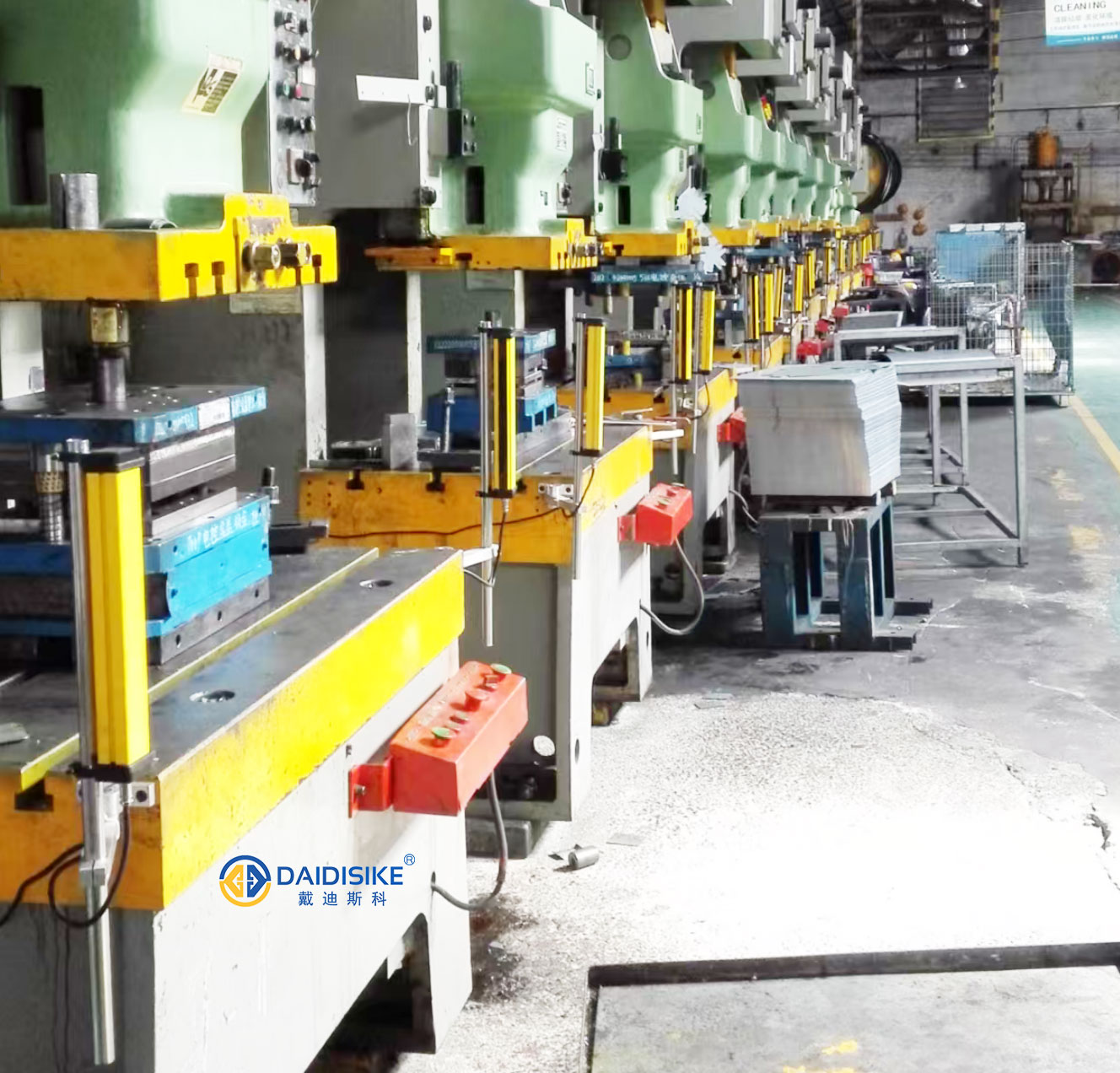
Step 1: The Z-Axis (Vertical Height Check)
It sounds obvious, but it is the most common mistake. The Emitter and Receiver must be mounted at the exact same vertical height. If the first optical axis (the bottom beam) on the Emitter is 2 inches higher than the first axis on the Receiver, the system will never sync.
The Fix: Do not just eyeball it. Grab a measuring tape and measure from the machine bed (or the floor) to the bottom cap of the Emitter. Do the exact same for the Receiver. Adjust the mounting brackets until they are perfectly level.
Step 2: The Y-Axis (Parallelism and Pitch)
Once the heights match, you need to ensure both sticks are perfectly plumb. If the Emitter is standing straight up at 90 degrees, but the Receiver is leaning forward or backward at 85 degrees, the beams at the top of the curtain will overshoot the sensors.
The Fix: Use a standard magnetic bubble level. Place it on the front face and the side face of both the Emitter and the Receiver. Make sure the bubble is dead center. Tighten the top and bottom screws evenly so you don't accidentally tilt the housing.
Step 3: The X-Axis (Twist / Yaw Alignment)
This is where things get tricky. Both units might be at the same height and perfectly plumb, but if they are slightly twisted on their vertical axis (facing slightly left or right), the infrared beams will “sweep” past each other.
The Fix: Start by loosening the rotational adjustment screws on your brackets just enough so you can manually twist the light curtain by hand.
- Keep the Emitter completely still.
- Slowly rotate the Receiver a few degrees to the left, then a few degrees to the right.
- Watch the LED indicator panel on the Receiver. You are looking for the moment the red light shuts off and the green light illuminates.
- Once the green light is steady, find the “center” of that green zone, and carefully lock down the screws.
The Hidden Killer: Machine Vibration
Here is a scenario that drives maintenance teams crazy: You perfectly align the safety light curtain on Monday. It runs flawlessly. But by Thursday afternoon, the red light is back on, and the press shuts down. What happened?
Vibration.
Heavy machinery like 200-ton stamping presses, shears, and forging hammers generate massive shockwaves with every stroke. If you are using cheap, thin metal brackets, or worse, L-brackets made of bent sheet metal, that continuous shock will slowly loosen the adjustment screws and shake the light curtains out of alignment.
Lock It Down with DAIDISIKE Heavy-Duty Brackets
Proper safety light curtain alignment isn't just about the initial setup; it is about keeping it locked in place for millions of machine cycles.
That is why at DAIDISIKE, we don't supply flimsy mounting hardware. We engineered specialized, ultra-thick Anti-Vibration L-Type and U-Type brackets. Made from reinforced steel, these brackets are specifically designed for suitable mounting applications; verify shock/vibration ratings, fastener torque and supported span against the exact installation.
Stop fighting phantom alignment issues and unnecessary machine downtime. If your current safety sensors cannot handle the shake, rattle, and roll of your factory floor, contact the DAIDISIKE engineering team today. We will set you up with robust light curtains and mounting hardware selected for the measured vibration and mounting conditions.