
Safety Light Curtain Installation & Wiring — Where Each Guide Lives
The page summarizes the wiring best practices and examples in dual channel OSSD, EDM, and PLC/Safety Relay circuits including DAIDISIKE DQC, MK, JER, DQT series light curtains and Mitsubishi FX5U, Siemens S7-1200, Omron and SICK safety relays.
These links organize the engineering topics; they do not establish that every listed model has dual OSSDs, EDM or a particular reset function. Confirm the exact order code, safety evidence and approved circuit before selection.
OSSD and EDM Principles and Terminology
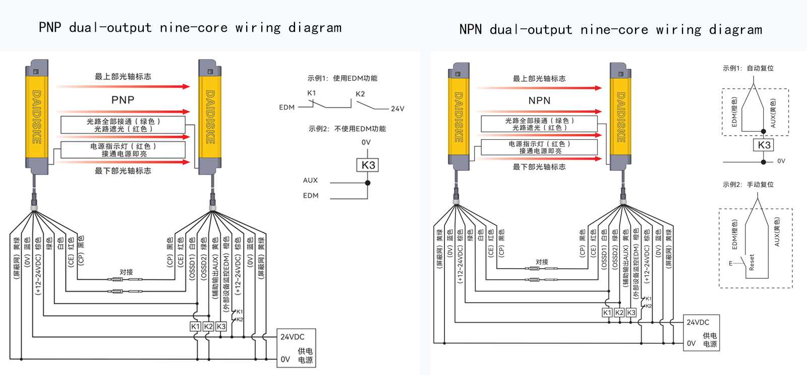
OSSD (Output Signal Switching Device) — An output safety output of a diagnosis often composed of two independent channels (OSSD1 and OSSD2). EDM (External Device Monitoring) is an element used to monitor the contacts of downstream contactors and safety relays (K1 / K2) for welded or failed contacts.
Check these functions against the required safety architecture and the exact device instructions; a wiring example does not award a Type, PL or SIL rating:
- OSSD: Verify the specified safety output channels and the downstream safety input compatibility, including test-pulse behavior.
- EDM loop: Where required, connect specified feedback contacts to the safety device that actually supports and performs external-device monitoring.
- Safety distance: Select the applicable ISO 13855 method using measured total stopping time, detection capability and access geometry, not only the sensor response time.
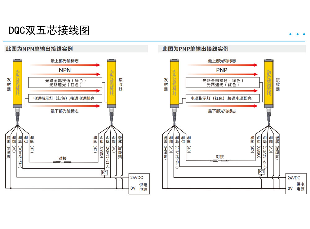
Looking for the drawings themselves? The complete light curtain wiring diagram library covers 5-core and 7-core color codes, NPN/PNP, OSSD + EDM loops, relay and PLC interfaces with model-specific limitations. For the feedback circuit specifically, use the EDM feedback and series NC contact guide.
Where a design uses a networked safety input rather than a local relay interface, the FSoE, PROFIsafe and CIP Safety integration guide separates protective data from ordinary diagnostics. For the equipment range before wiring, compare safety relay modules and their documented input functions.
Mitsubishi FX5U: Diagnostic Status I/O Mapping
The FX5U example is an ordinary-PLC diagnostic map. It does not replace the safety controller or its feedback loop.
For signal ownership and input-common checks, see the dedicated guide: Mitsubishi FX5U diagnostic I/O mapping.
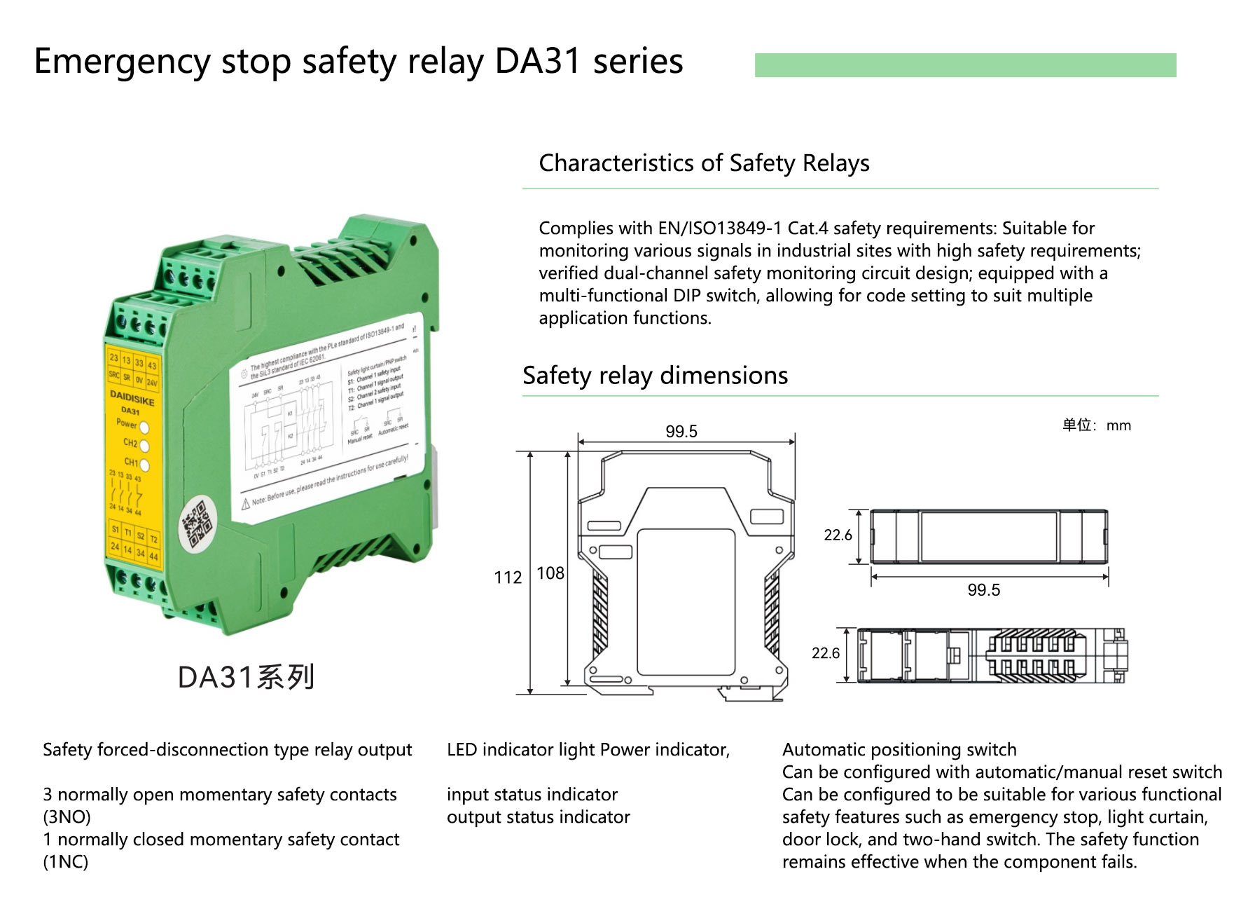
| Signal | Terminal | Function / Remarks |
|---|---|---|
| Guard status copy | FX5U X0 (example) | Approved auxiliary output for indication only; not OSSD channel A |
| Safety-system ready copy | FX5U X1 (example) | Independent diagnostic signal; not OSSD channel B |
| Feedback healthy copy | FX5U X2 (example) | Status from the safety device, not the actual EDM feedback loop |
| Reset status copy | FX5U X3 (optional example) | Indication only; reset/restart remains in the validated safety system |
| +24V / 0V | Documented power supply | Verify voltage, polarity, input common and circuit protection for the exact units |
IMPORTANT NOTE: FX5U is not a safety PLC. Safety stops must be carried out by the safety system and its final switching devices. Ordinary PLC diagnostics must not make the protective-stop, EDM or reset decision.
Standard Siemens S7-1200: Diagnostic Status Programming
Separate standard-CPU diagnostics from an approved fail-safe CPU/I/O design. The S7-1200 input wiring and diagnostic example explains that boundary and the model-specific checks.
Diagnostic status example (pseudo-code, no safety or reset commands):
// Diagnostic illustration only, not safety application code.
// Inputs are approved auxiliary/status copies from the safety system.
// Do not wire this example to the safety outputs or reset circuit.
StatusForHMI := GuardStatusCopy AND SafetySystemReadyCopy;
MaintenanceMessage := NOT FeedbackHealthyCopy;
// No safety-stop, EDM, reset or restart decision is made here.
Consult the Siemens S7-1200 functional safety manual for fail-safe configurations; the ordinary diagnostic example above is not that implementation.
DAIDISIKE DQC/MK/JER/DQT Series + Safety Relay: Omron / SICK
The light curtain and safety relay wiring guide separates sensor inputs, protective outputs and model-dependent feedback. Matching wire colors or brand names is insufficient.
- Omron G9SA: Verify the exact relay variant, permitted input devices and approved circuit. Do not assume an OSSD connection is supported simply because the supply is 24 V.
- SICK UE Series: Check the specific model's safety input, reset and external-device monitoring instructions rather than transferring a circuit across the entire family.
- DAIDISIKE Controllers: Confirm output compatibility and required functions for the ordered module. Do not assume EDM or reset support from the phrase “safety relay”; DQSRN does not provide manual reset, automatic reset or EDM.
Installation and positioning tips, false triggering and troubleshooting
Start with the alignment and false-trip diagnostic guide to distinguish optical, mounting and electrical causes. Keep the machine safely stopped during fault investigation.
- Alignment problems: Follow the specified alignment sequence and indicators, then test the full protected field. A stable status indicator alone is not a coverage test.
- Welding arc/strong light interference: Check the stated ambient-light limits and approved shielding. Do not add an unapproved optical filter or change a protective field to suppress trips.
- Reflective surface interference: Use the model-specific reflective-surface distance and test procedure. No universal 300 mm clearance or blanking setting is a substitute for those checks.
- EMI: Follow the sensor and drive manuals for cable segregation, shielding and earthing. Separate optical symptoms from power or electrical interference faults.
- Foggy and dusty areas: Check ingress, condensation and optical contamination separately. An IP rating does not guarantee visibility through fog or a dirty window.
Shielding, grounding, wiring distance and EMC recommendations
- Use specified cables and permitted lengths; route sensor circuits separately from drive/power wiring according to the equipment manuals.
- Follow the prescribed shield termination and protective-earth arrangement; single-ended grounding is not a universal rule.
- Use the specified supply, protection and isolation arrangement; confirm voltage drop and load requirements.
- Identify terminals and signals clearly so diagnostics can be checked without bypassing the safety feedback or reset circuit.
Commissioning Checks: Protective Stop, Feedback and Restart
- Test the actual sensor and safety controller response using approved test objects and the documented commissioning procedure. Prevent hazardous motion during the test.
- Where EDM is required, verify fault detection using the approved procedure. For a lockout, follow the EDM lockout and contactor feedback diagnosis; never bridge feedback contacts or force a reset.
- Verify the required reset and restart behavior in the safety system. Clearing the light field must not create an unintended hazardous restart.
- Measure total stopping performance and record the applicable ISO 13855 distance calculation and access checks.
- File configuration, test results and inspection intervals derived from the risk assessment and equipment instructions.
Guide Resources and Tools
Frequently Asked Questions (FAQ)
Q1: Is the OSSD NPN or PNP?
A: Output polarity and safety functionality are separate checks. Read the exact sensor and safety-input manuals for output type, diagnostic test pulses and approved connection. A PNP or NPN switching output is not automatically an OSSD, and a model name does not establish automatic polarity selection.
Q2: Is EDM mandatory?
A: The required external-device diagnostics depend on the validated safety architecture and device instructions. Where contactor feedback is required, suitable mirror contacts are monitored by a safety device with that function, not an ordinary PLC. An EDM connection alone does not establish a PL or SIL rating.
Q3: Can an ordinary PLC cut off the safety circuit directly?
A: An ordinary FX5U or standard S7-1200 input/program is not the safety logic for personnel protection. The protective stop, output-device monitoring and restart behavior must be implemented and validated in the appropriate safety system. Standard PLC inputs may receive approved auxiliary status copies for diagnostics. Fail-safe CPU and I/O configurations require their own approved design.