
Safety Light Curtain NPN/PNP, PLC, Safety Relay — What They Are and How to Wire Them (with DAIDISIKE DQE Examples)
Whether you’re a plant engineer or a buyer, this guide will help you quickly understand safety light curtain output types and wiring. We’ll break it down step by step and use DAIDISIKE DQE series as the running example.
Content updated: 2026-09-06. This page explains polarity and evaluation choices. The exact DQE safety rating and dual-OSSD availability remain model-document questions, not consequences of its NPN/PNP label.
For the wider design sequence—device identification, cabling, reset/feedback and acceptance—use the installation and wiring knowledge hub. This page stays focused on output polarity and evaluator selection.
What is a Safety Light Curtain?
A safety light curtain is the “electronic eye” of machine guarding. It creates a protective field using opposed infrared beams. When any beam is interrupted, the curtain signals the validated control system to stop hazardous motion. Many documented models use dual self-monitoring safety outputs (OSSD1/OSSD2) while others use a different approved safety interface. The complete function must stop the machine within the required safety distance. Typical standards involved include IEC 61496, ISO 13849 and ISO 13855. It is widely used on presses, robot arms, hydraulic machines and automated lines.
NPN vs PNP Output Types
NPN and PNP describe transistor current direction. Some protective devices use monitored solid-state outputs with a particular polarity, while ordinary sensors can use the same electrical terms without a safety rating. Read the actual output description and safety documentation together.
- PNP: when the transistor conducts it sources current from the positive supply; the receiving load/input is towards 0 V. Whether clear or blocked field means conducting depends on the documented logic.
- NPN: when the transistor conducts it sinks current towards 0 V; the receiving load/input is towards +V. Do not rely on a vendor's NPN/PNP input label without reading the current path.
There is no general noise-immunity or safety-level advantage from polarity alone. Electrical compatibility is one requirement; the exact device safety capability, diagnostic behaviour, architecture and validation determine whether the required PLr/SIL can be met.
PLC vs Safety PLC
A standard PLC is the “brain” for process control, but it is not safety-certified and cannot alone handle emergency stop functions.
A Safety PLC (or a safety relay) includes cross-monitoring, self-tests and fault detection to meet ISO 13849 or IEC 61508. Think of it as a dedicated safety guardian that reliably processes the curtain’s OSSD signals so the machine stops when danger is present.
Rule of thumb: simple stop chains → use a safety relay; complex interlocks → use a safety PLC.
What a Safety Relay Does
A safety relay evaluates specified safety inputs and controls an approved output circuit. Available input types, reset, feedback/EDM and diagnostics vary by model. An auxiliary contact is not automatically an EDM input, and a relay rating does not confer that rating on the entire machine function. See the distinction between component capability and full-function PL/SIL.
For a candidate such as DA31, obtain the exact version's approved connection and input compatibility before assigning terminals or required functions. Do not assume it accepts every NPN/PNP output. DQSRN does not provide manual/automatic reset or EDM.
DQE Wiring Guide (NPN / PNP)
The historical six/seven-core catalogue illustration conflicts with the owner-confirmed physical-manual channel assignment: its right-hand heading also says NPN while the drawing is labelled PNP. It is not reproduced here as an installation drawing. Obtain the delivered model's controlled cable schedule.
- Record supply, return, synchronisation and every output separately.
- Confirm whether outputs are ordinary transistor signals or an approved monitored safety interface.
- Map documented safety outputs to separate compatible safety inputs; terminal names come from the selected evaluator manual.
- BN (brown): +24 VDC supply (+)
- BU (blue): 0 V (–)
- WH (white): OSSD1 in the previously owner-confirmed physical-manual mapping; verify the delivered variant.
- BK (black): OSSD2 in that same physical-manual mapping; do not extend it to a different cable.
- Other conductors: identify every function from the exact cable drawing. Do not assign reset, CP or CE from a guessed colour.
Verify before you land a wire. Colour is not a standard. It varies by series and even by production batch, and it does not carry across manufacturers at all — on a DQC 5-core the white conductor is the transistor output and black is the CP synchronisation line, which is a completely different function from the DQE mapping above. Identify every conductor by function against the manual that shipped with your unit, and confirm with a meter before power-up. See the safety light curtain wiring diagram library for series-specific evidence checks and the limits of colour-based identification.
Shielding and bonding: follow the specific device and machine EMC design. Protective earth, shield/functional earth and 0 V are distinct; there is no universal single-end termination or permission to substitute 0 V for PE.
- Never merge OSSD1 and OSSD2. They must land on two independent safety inputs.
- Use the approved cable construction, length and routing. Do not improvise conductor pairing, fuse placement or EMC separation from a generic example.
Three Common Wiring Schemes
- Approved PNP safety outputs → compatible safety relay: a candidate for a defined stop function where the relay supports the exact inputs, required reset/feedback and final elements. Isolate before wiring and validate the completed design.
- Approved PNP safety outputs → compatible safety controller: useful where zoning or several safety functions justify programmable evaluation. Use safety-rated I/O and validated logic; a drive STO function alone does not control coast-down, gravity or stored energy.
- Documented NPN safety interface → explicitly compatible safety evaluation: consider only when the manufacturer approves that pairing. Do not add ordinary pull-ups or an interposing relay as a presumed safety conversion.
How to Choose: NPN or PNP? Relay or Safety PLC?
Step 1 — Look at the downstream safety input. Read its approved output/input interface, load limits and diagnostic-pulse requirements. Select PNP or NPN only when the exact combination is supported; do not infer support from brand or voltage alone.
Step 2 — Consider system complexity. A single stop chain is cost-effective with a safety relay. If you must integrate multiple safety functions, a safety PLC scales better.
Power-source check before selection
Confirm the actual supply voltage, tolerance, permitted source class, current demand, protection and bonding from the device manual. If the machine has only mains power, specify a suitable approved power supply or documented controller build. Do not assume a DA31 relay converts AC to the required sensor supply.
Six-Step Commissioning & Acceptance
- Documentation: exact model/manual, safety evidence, approved diagram and risk assessment; detection capability is not beam pitch.
- Isolated electrical inspection: lock out hazardous energy; verify supply, protection, bonding and cable requirements without universal ripple or grounding values.
- Output/evaluator compatibility: separate specified safety channels; no raw OSSD branching to ordinary PLC inputs and no unapproved polarity conversion.
- Required feedback/reset: identify the actual implementing device and approved configuration. Validate mirror-contact feedback and restart prevention where required.
- Detection and stopping: with hazards disabled, use the specified test piece along the complete required paths and boundaries; measure machine stopping performance under a separate controlled procedure and apply the relevant ISO 13855 method.
- Fault validation and release: follow an approved safe test plan, not live wire-opening or contactor-shorting instructions. Record settings, results and authorization before service.
Common Errors & Troubleshooting
- Merging OSSD channels: loses redundancy and is unsafe.
- Landing on a standard PLC: the PLC sees the signal but provides no certified safety integrity—non-compliant.
- Grounding issues: floating grounds cause electrical or EMC problems—apply the exact protective-bonding and shield instructions.
- Defeating required feedback: can conceal a failed final element. Implement the approved monitoring architecture and do not bridge faults.
- Insufficient safety distance: the machine stops too late—calculate and verify against ISO 13855.
- Unapproved cabling: wrong routing, length, shield termination or connector can violate interface/EMC limits. Use the exact installation instructions.
DQE Application Notes
- Six/seven-core versions: the local DQE product page acknowledges inconsistent legacy output descriptions and no published Type/PL classification. Resolve the exact safety evidence before personnel-protective use.
- Polarity: the receiving interface must support the documented output, including diagnostic behaviour where safety OSSDs are claimed. A core count does not establish that support.
- DQET built-in controller: confirm the exact terminal schedule and safety-function scope. A built-in relay stage does not prove permission to omit required safety evaluation.
- Candidate DA31: confirm its exact manual, input type, output use and required reset/feedback arrangements; no IN1/IN2 or EDM assignment is invented here.
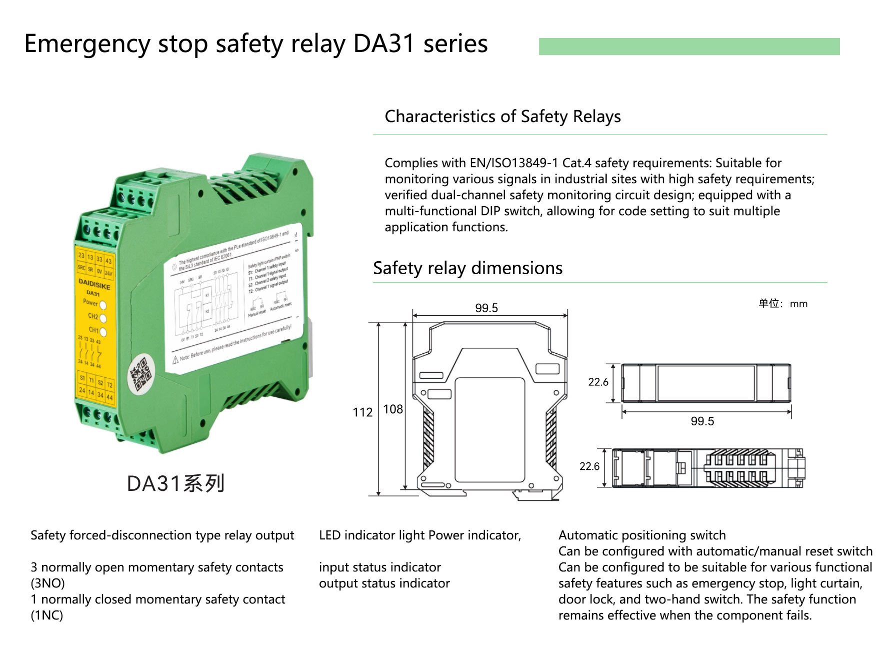
Catalogue appearance and outline only. Printed marketing functions are not a complete approved installation manual or proof of this device pairing.
Selection Checklist
- Resolution: 14 mm (finger), 30 mm (hand), or larger for body/area
- Protected height, operating range, response time
- Output type and integrity: exact approved interface, polarity, load and pulse compatibility
- Logic device: safety relay (simple) or safety PLC (complex)
- Environment: IP rating (e.g., IP67), anti-vibration, oil resistance, EMC
- Cabling: approved construction, length, connectors, routing and bonding
- Standards: target PLr, ISO 13855 safety distance, IEC 61496
- Exact-model declaration and applicable certificate/test-report scope; CE marking is not itself an independent certificate.
FAQ
Why does merging OSSD channels still stop the machine?
A simple interruption test may still stop motion even when channels are incorrectly merged. That does not validate the intended two-channel fault detection. Keep raw OSSDs separate, use compatible safety inputs and validate the exact architecture; never merge, series-wire or parallel them to ordinary PLC inputs.
Do I need new hardware to switch from NPN to PNP?
Choose a device with the correct approved safety interface. An ordinary interposing relay or polarity converter must not be assumed to preserve OSSD diagnostics, response or PL/SIL. A conversion is acceptable only when explicitly covered by the equipment's safety documentation and a validated design; otherwise reselect the hardware.
How do I confirm the wiring is correct?
Identify exact models and manuals, inspect isolated wiring, then perform a planned controlled validation with hazardous motion prevented during detection tests. Use the specified test piece along the complete required paths and boundaries, validate the required stop/reset/feedback and fault behaviour safely, measure full machine stopping performance and record acceptance before service.
Sources: the DQE product documentation and unresolved safety-rating note, SICK deTec4 Core instructions for compatible safety-output evaluation and controlled testing, and ISO 13855:2024 for positioning methodology. A manufacturer's example applies only to its specified equipment.