
OSSD + EDM: DQC × Mitsubishi FX5U Wiring (with I/O Map, Reset & Commissioning)
Keep two paths separate: both DQC OSSD channels feed compatible qualified safety logic; an ordinary Mitsubishi FX5U receives only auxiliary diagnostic status. This guide maps those status signals while reset, EDM where required, and the protective stop remain in the validated safety circuit.
Start with the safety installation and wiring guide to establish the sensor–logic–actuator circuit. The ordinary FX5U program cannot implement this safety function. See the Mitsubishi FX5 hardware manual before selecting interfaces.
This page covers the FX5U specifically. For the wiring that comes before the PLC — cable colour codes, NPN/PNP hookups, OSSD and EDM loops, safety relay terminals and the commissioning trip test — see the complete light curtain wiring diagram hub.
1) OSSD / EDM principles & selection (PNP/NPN)
OSSD is a safety switching output, normally evaluated as two channels by compatible qualified safety logic. Test pulses and discrepancy limits are device-specific; an ordinary PLC scan is not a suitable substitute.
EDM monitors specified external-device feedback where required by the architecture, so a failed final switching device prevents restart. Locate this function in the documented safety controller or device that actually supports it.
| Item | Design check | Record |
|---|---|---|
| Type / PL / SIL | Select from risk assessment and exact device evidence | A component rating is not the achieved system rating |
| OSSD | Both channels to compatible safety inputs | Test-pulse compatibility and response time |
| EDM / reset | Qualified safety logic where required | Exact function and terminal diagram |
| PNP / NPN diagnostics | Compatible auxiliary output and ordinary PLC input | Exact module input/common arrangement |
| Safety distance | Applicable ISO 13855 method and measured stopping time | Separation-distance calculation inputs |
2) Wiring Option A: PNP (sourcing, recommended)
A sourcing auxiliary output may feed a compatible ordinary PLC input. Follow the exact input-module diagram for its reference terminal and supply; do not route the two protective OSSD channels to these diagnostic inputs. Wire the curtain transmitter/receiver to its factory terminal map and its outputs to qualified safety logic.
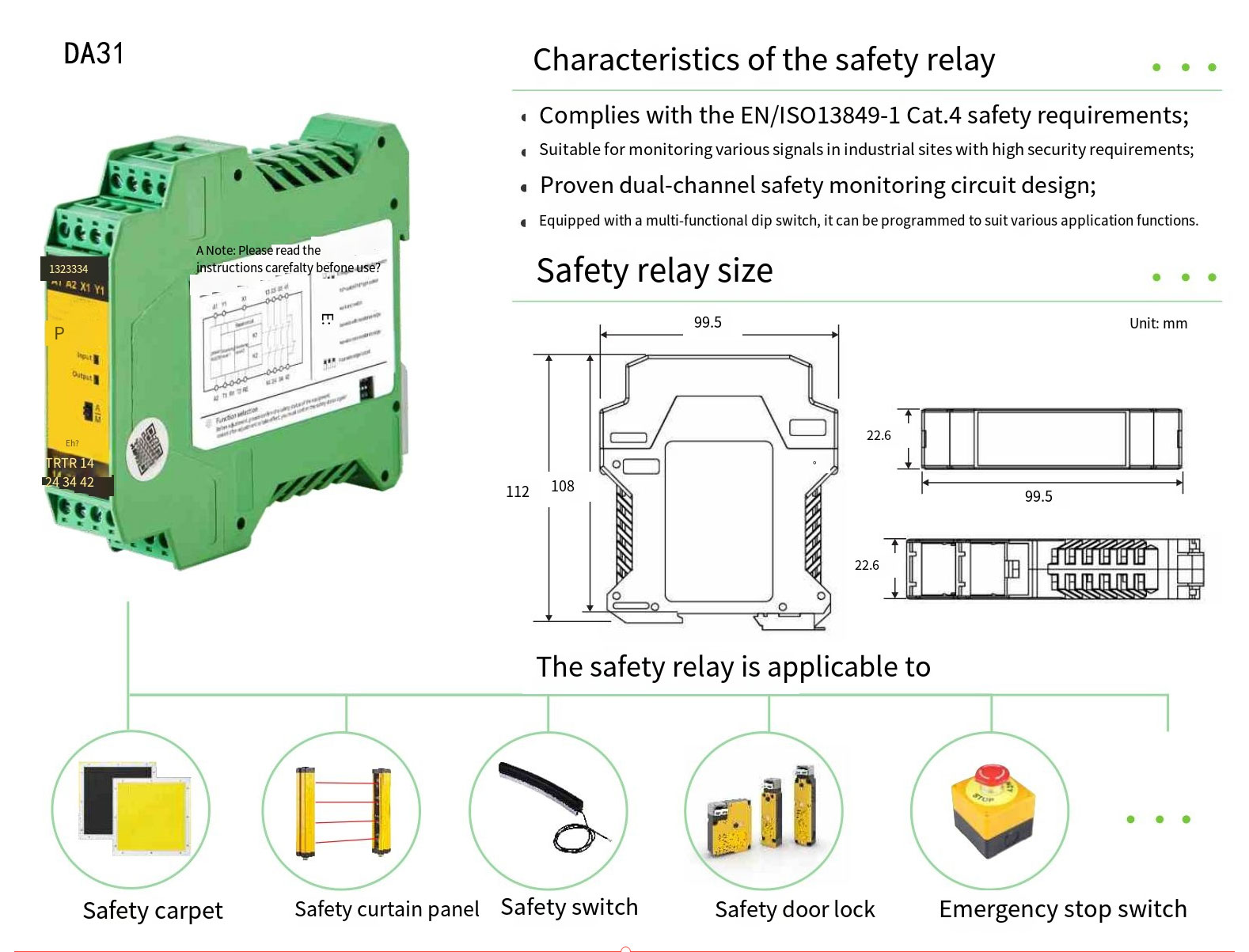
Key points
- Connect both OSSD channels to compatible safety inputs, with protection and routing specified by their manuals.
- Keep monitored reset and any required contactor feedback in qualified safety logic.
- Obtain diagnostic copies only from documented auxiliary outputs; do not load or branch protective channels without explicit manufacturer approval.
- Loss of ordinary PLC power or communications must not defeat the protective stop.
Typical I/O (PNP)
| Signal | Example address | Function |
|---|---|---|
| AUX_READY | X0 | Controller ready display only |
| AUX_FAULT | X1 | Controller fault diagnostics |
| AUX_EDM_STATE | X2 | Optional status copy, not the feedback loop |
| AUX_RESET_STATE | X3 | Optional reset-status copy, not reset control |
3) Wiring Option B: NPN (sinking)
Use an NPN auxiliary diagnostic output only with a module explicitly documented to accept it. Follow the exact FX5U input/common terminal arrangement. This is not a software polarity inversion and does not authorize substitution of the curtain's protective output configuration.
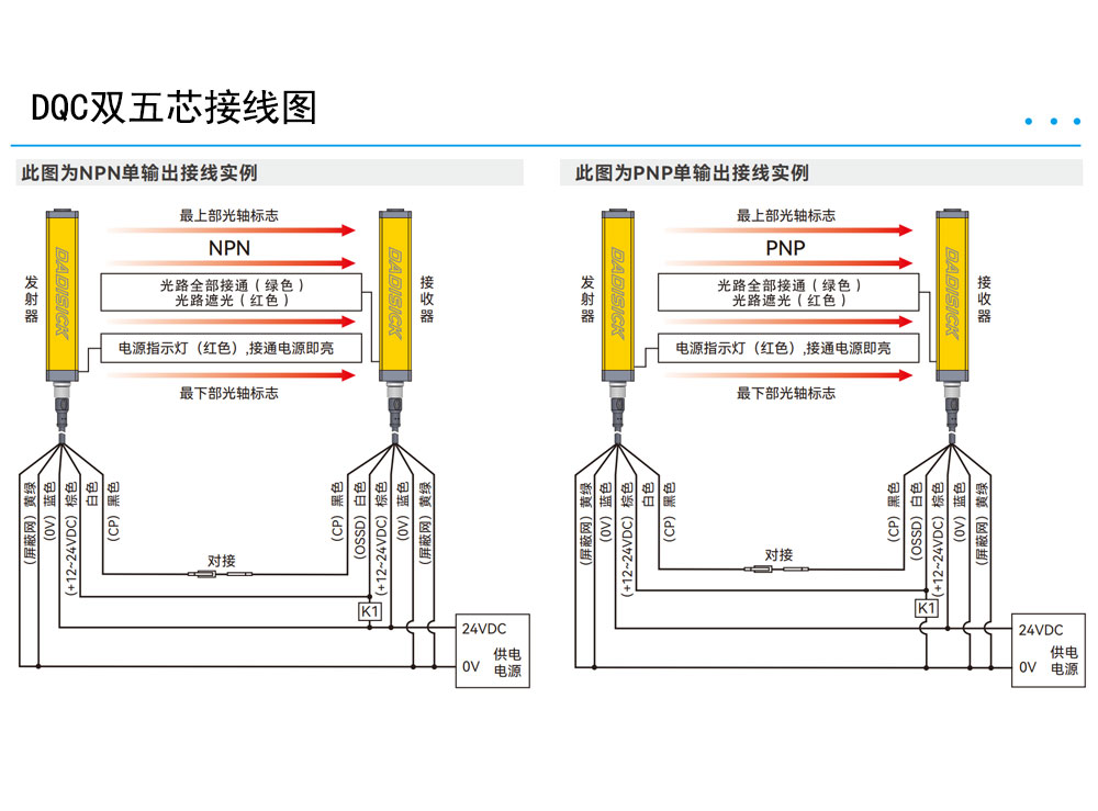
4) I/O map & naming convention
Record actual terminal assignments separately from symbolic names. The example below is an auxiliary diagnostic I/O list, not a protective circuit. If a selected controller lacks a listed auxiliary output, omit that signal rather than creating a safety-channel tap.
| Variable | Example address | Source | Purpose | Boundary |
|---|---|---|---|---|
| AuxReady | X0 | Controller auxiliary output | Ready display | No safety permission |
| AuxFault | X1 | Controller auxiliary output | Fault display | Not channel evaluation |
| AuxEdmState | X2 | Optional auxiliary output | Feedback-state display | Actual EDM stays in safety logic |
| AuxResetState | X3 | Optional auxiliary output | Reset-state display | Actual reset stays in safety logic |
| ReadyDisplay | Project-assigned bit | AuxReady copy | HMI | No start latch |
| FaultDisplay | Project-assigned bit | AuxFault copy | HMI | No safety interlock |
ST diagnostic illustration
// Diagnostic illustration only. Assign and declare symbols in the actual project.
// Sources are documented AUXILIARY status outputs from qualified safety logic.
// NOT OSSD evaluation, EDM, reset or machine-start permission.
ReadyDisplay := AuxReady;
FaultDisplay := AuxFault;
// The protective stop operates independently of these display bits.
Declare symbols, assign device addresses and check status validity in the actual project. This snippet does not implement OSSD evaluation, EDM, reset or enable-to-start logic.
5) Reset strategies (manual / two-stage / rising edge)
- Restart prevention: use the risk-assessed reset mode, including measures for a person remaining inside the hazard zone.
- Monitored action: implement the qualified safety controller's documented reset timing and edge behavior, not an ordinary PLC double-press timer.
- Separate start: reset must not itself initiate hazardous motion; do not latch start permission in the diagnostic example.
- Visibility: locate reset outside the hazard zone with adequate visibility and additional measures for hidden occupancy.
6) Commissioning & self-test (scope/meter checkpoints)
- Equipment and polarity: check exact order codes, terminal diagrams, supply, bonding and auxiliary I/O compatibility.
- Protective response: interrupt the field with the specified test piece; measure and document the complete stopping response. Evaluate channel discrepancy and test pulses with the approved safety-input configuration.
- Fault response: secure hazardous energy and use only manufacturer-approved fault simulations. Do not mechanically hold a live contactor or bypass a protective output.
- Reset: verify held/stuck/reset conditions and that field clearance or power recovery does not cause unintended restart.
- Separation distance: apply the relevant ISO 13855 positioning method using measured stopping time, detection capability and actual approach geometry. The linked calculator elsewhere on this page is restricted to its historical reach-through domain, not a complete ISO 13855:2024 assessment.
- Diagnostic independence: loss of PLC power or status communication must not defeat the safety stop. Archive approved waveforms, settings, drawings and test results.
Self-test record template (copy to CSV)
Item,Test,Expected,Actual,Result,Notes
1,Beam interruption,Safety outputs off within documented response time,,,
2,Approved channel fault simulation,Documented safety-input fault response,,,
3,Approved EDM fault simulation,Restart inhibited where EDM is required,,,
4,Monitored reset,Documented reset and restart prevention validated,,,
5,Safety distance,Measured total stopping time and applicable method recorded,,,
6,Auxiliary display loss,PLC or communication failure cannot defeat safety stop,,,
7) Cabling & EMC (shielding/grounding/separation)
- Follow equipment-specific routing and separation distances for OSSD, feedback, auxiliary signals and drive/power cables.
- Terminate shields and protective bonding according to the documented EMC design; single-point termination is not a universal rule.
- Verify supply capacity, protective devices and voltage under load; isolate interference sources without interrupting required safety bonding.
- Keep terminal numbers, cable markers and the diagnostic I/O map consistent with the as-built drawings.
- Select an enclosure and connector combination suitable for the actual dust, liquid and cleaning exposure; ingress ratings do not establish optical immunity.
8) Alignment tips & interference troubleshooting
- Alignment: use the receiver's documented alignment indication, secure brackets, then repeat the full protective-field test.
- Welding or strong light: use manufacturer-approved shielding or placement changes. Arbitrary filters may reduce detection performance; do not hide faults with muting.
- Reflections: maintain the manufacturer's range-dependent reflective-surface clearance on all sides, not a universal 300 mm gap.
- Mist and dust: clean approved optical surfaces and investigate deposits or condensation. A higher IP rating does not stop airborne material interrupting a beam.
9) Downloads & tools
- OSSD/EDM wiring pack (PNP/NPN, FX5U/S7-1200, relay matrices)
- ISO 13855 safety distance calculator
- DQC quick selector (resolution / height / range)
FAQ
Why prefer PNP? Can I use NPN?
This choice concerns auxiliary diagnostics only. Match the exact PLC input module and auxiliary output manual. Do not change supply/common polarity unless that input circuit explicitly supports it; OSSD channels remain on compatible qualified safety inputs.
Can I skip EDM?
The validated safety architecture determines external-device monitoring. Where required, qualified safety logic monitors specified contactor feedback and inhibits restart on faults. Ordinary PLC logic cannot replace EDM; verify that the selected controller actually supports it.
Can the PLC cut the safety circuit directly?
An ordinary FX5U must not execute the protective function in this example. Qualified safety logic and final switching elements stop the hazard independently of ordinary PLC execution or communications. Auxiliary display bits are not safety permission.
Illustrations used on this page
- Fig. 1: Safety relay module context — replaces the generic PNP diagram for visual context.
- Fig. 2: Safety light curtain device shot — used to indicate the NPN variant section.
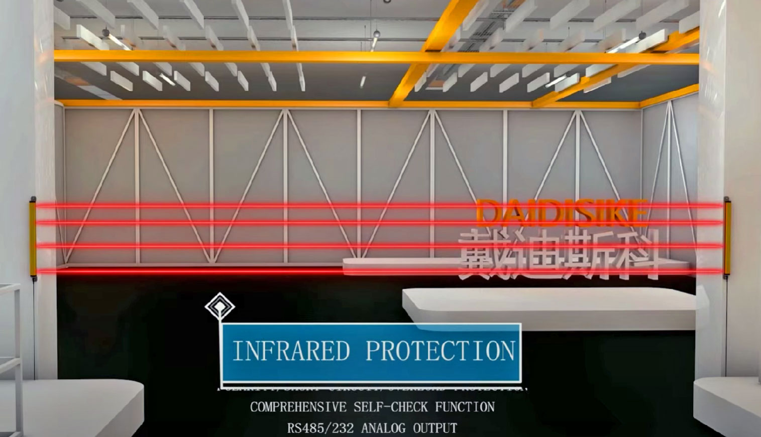
- Fig. 3: Photoelectric sensor close-up — used to visualize commissioning checkpoints.