
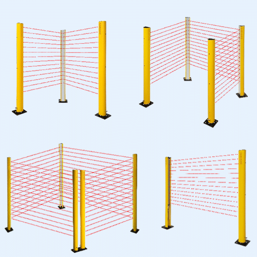
The zone configuration basics article covers the ground a newcomer needs — what a warning field is, what a protective field is, how teach-in works at the simplest level. This piece picks up where that one stops. The question now is not “what is a protective field” but “how do I configure twelve of them, switch between them safely, prove the switch happens at the right moment, and keep the whole arrangement auditable”.
Why a single field is not enough
One fixed field can cover every mode if it encloses the worst-case stopping envelope, but may restrict docking or aisle access. Field depth cannot be inferred from speed alone: response and control delays, complete braking distance, load and required allowances all contribute. A smaller docking field is acceptable only for the safely limited motion for which it was validated.
The whole point of multi-zone configuration is to let one scanner present the right field for the right moment — faster speed, deeper field; turning, asymmetric field; narrow aisle, slimmer field with the warning band pulled in tight. Done well, this is how a mobile robot achieves both safety and throughput. Done badly, it is how field switching becomes a way of hiding nuisance stops — an audit failure waiting to happen.
Field sets — what a scanner actually stores
Internally, a safety scanner stores a list of field sets, sometimes called monitoring cases. A field set is a complete configuration unit: one protective field shape, one or more warning field shapes, the response time assignment for that case, and the conditions under which this set becomes active. The scanner remembers the entire library in non-volatile memory and can hot-swap between sets within its response time.
The number of available field sets is one of the more honest markers of scanner class:
- Compact obstacle-avoidance scanners typically offer four to eight switchable sets. That is enough for an AGV with three speed bands plus a turning case.
- Mid-range industrial safety scanners commonly support sixteen to thirty-two switchable cases — suitable for AMRs that handle multiple zones, dock approaches and shared-space corridors.
- Flagship platforms can hold roughly seventy independent configurations, intended for vehicles operating across very different environments or for stationary cells that cycle through many distinct hazard states.
More is not automatically better. Seventy field sets is seventy things you must validate, document and re-validate every time the firmware moves. Most real installations end up using six to twelve and that is plenty.
What triggers the switch
Three trigger families cover almost every real installation. They can be combined — an AGV often uses two of them at once.
1) Vehicle speed via an encoder
Some scanners accept encoders directly; others depend on a safety controller to evaluate speed and select a monitoring case. Use the architecture permitted by the exact manuals. Encoder A/B quadrature provides direction information but does not by itself prove PL d. Evaluate redundancy, diagnostics, wheel slip and mechanical coupling. Derive thresholds from measured stopping performance and include field-switching latency.
A few scanners accept an absolute encoder or even a safety analog speed signal instead, useful where the geometry of the vehicle makes a wheel encoder awkward. Whichever interface you use, the source must be PLd-rated end to end — ISO 3691-4 is explicit that the speed signal feeding field selection on a driverless truck is itself part of a safety function.
2) Machine state from a safety PLC
Common on stationary cells. The safety controller knows what mode the machine is in — setup, automatic, robot at home, robot extended, conveyor running forward, conveyor running reverse — and signals the scanner over a small number of dual-channel discrete inputs or, increasingly, over a safety fieldbus. The scanner maps each input combination to a field set. Two safe inputs already give you four states; four inputs give you sixteen.
This is the cleanest model when the application has clear, discrete modes. It is harder to argue against in an audit because the trigger is deterministic and the safety chain is short.
3) Position from a localiser
A vehicle that knows where it is on a map can pre-select a field set just before it enters a known geography — the narrow aisle, the pick station, the docking bay. Position triggers are almost always layered on top of speed switching rather than replacing it, because the localiser itself is rarely safety rated. A common pattern: position selects a candidate field set; speed decides which protective depth inside that set is active; the scanner enforces the final geometry.
Trigger types compared
| Trigger | Effective response | Wiring complexity | Typical use |
|---|---|---|---|
| Incremental encoder (dual channel) | Use documented speed evaluation and switching delays | Moderate (two encoder channels, wheel mount) | AGV, AMR speed-based fields |
| Absolute encoder / safety analog | Continuous | Moderate | Drives where wheel encoders are impractical |
| Discrete safe I/O from PLC | Step change at PLC scan rate | Low (a few dual-channel inputs) | Stationary cells, mode-based switching |
| Safety fieldbus from controller | Step change at bus cycle | Low cabling, higher integration effort | Modern integrated machinery |
| Localiser position (non-safety) | Pre-select only, gated by safe signal | Software | AMR geographic pre-selection |
Sizing each field with ISO 13855
Separate fixed-machine safeguard positioning under ISO 13855 from mobile-truck detection-distance design under ISO 3691-4. For a vehicle, include travel during sensing and control delays, measured braking distance to standstill and required allowances. Do not substitute vehicle speed into a fixed-machine human-approach formula and treat the result as a complete truck design.
The total response time you plug in is the worst-case sum of scanner response time, controller reaction time, brake actuation time and any latency in the safety chain. Run the formula for each speed band you plan to allocate a field set to, add a margin for tyre wear, payload variation and gradient, and you have the minimum protective field depth for that band. Anything smaller than that is by definition unsafe; anything much larger throws throughput away. The 2024 edition of ISO 13855 keeps the same fundamental approach with refinements to the constants and a tightened treatment of detection-capability margin.
Teach-in — what it does and what it does not do
The teach-in tool inside a scanner configuration package lets you capture the static contour of the protected area as a starting shape for a field. Park the AGV in position, take a teach scan, and the scanner now knows where the racks and walls and floor features actually are. From that contour you sketch the protective and warning fields, either by tracing the contour with a software offset, by drawing polygons or by specifying rectangles.
What teach-in does not do is verify that your field is large enough. The depth you set still has to satisfy the ISO 13855 calculation for the speed and response time of the case it belongs to. After every teach-in cycle you should:
- Measure the field on paper against the calculated minimum depth for that speed band.
- Walk a calibrated test piece into every edge of the protective field and confirm the safety outputs switch.
- Record the test result with date, witness, scanner serial number and field set identifier in the safety file.
Common configuration patterns
Three-band AGV pattern
The workhorse. One field set per speed band — slow / medium / fast. The protective field grows with speed, the warning field stays roughly proportional, and a separate “turning” field set handles the asymmetric geometry when the vehicle is rotating. Four sets total, sometimes six if forward and reverse travel each get their own pair.
Mode-based stationary cell
Two to four field sets driven by safe inputs from the cell PLC. Typical cases: automatic mode (full protective area), teach mode (reduced area around the operator pendant), maintenance access (entire field disabled with the cell power-isolated).
Pedestrian-shared corridor
A warning field can request an early slowdown. The protective field must still cover the permitted speed if that non-safety request fails. Use a smaller field only after a suitable safety function confirms or enforces the lower speed. A warning output alone cannot establish a safe walking-pace condition.
Fork-truck shared zone
One of the hardest. The protective field has to ignore the AGV’s own forks at certain extension positions while still detecting a pedestrian. This is usually solved with a separate field set per fork height, switched from a discrete safe signal, and a contour reference that includes the forks at that height.
Common mistakes
- Muting abuse. Using field switching to effectively mute the protective field whenever the machine misbehaves. The field that runs when something is wrong is usually the field a person gets hurt in.
- Field overlap conflicts. Two sets that can both legitimately be active at the same moment because their switching conditions are not mutually exclusive. The scanner will pick one — usually the wrong one.
- Switching delay too long. A safety function response time that includes scanner response, controller scan time and switching delay can quietly exceed the stopping distance the field was sized for. Re-run the ISO 13855 sum any time you add a step to the switching chain.
- Default-to-smallest fallback. On signal loss or encoder fault, verify the documented safe state. A larger field does not automatically make continued motion safe when speed or direction is unknown.
- Treating teach-in as design. Teach-in captures the room. It does not size the field.
Edge cases worth thinking about
Turning AGVs. A vehicle rotating in place has a stopping distance defined by angular momentum, not linear speed. Use a dedicated turning field set with a circular or sector shape, triggered by the speed of the inner wheel falling below a threshold while the outer wheel is moving.
Narrow aisles. A protective field sized for the aisle width may overlap the rack profile and trip continuously. The right answer is a teach-in that includes the rack contour plus a contour-following protective field; the wrong answer is to shrink the field until it stops tripping.
Outdoor sections. Confirm the exact model is approved for the environment. Do not relax detection settings to hide weather faults. Any permitted filtering change requires renewed response-time and stopping-distance checks.
Loaded vs unloaded. A laden vehicle takes longer to stop. Either size every field for the worst case (laden) or add a load-state input to the safe signal set so the scanner can pick the right field depth.
Validation — the part nobody enjoys
Validation is per-configuration. A scanner that passes its factory acceptance test on one field set is not validated for any of the others. For each field set you have to:
- Force the switching condition that selects this set and confirm it becomes active (the scanner’s diagnostic output normally indicates the active case).
- Walk a calibrated test piece into the protective field at multiple points around its perimeter and confirm the safety outputs switch within the response time.
- Measure the machine stopping distance from each safety output switch and confirm it falls inside the field boundary.
- Repeat the test piece check at the very edge of the warning field to confirm the non-safety reaction works.
- Induce relevant faults — disconnect an encoder channel, mismatch two PLC inputs — and confirm the documented safe response under a controlled validation procedure.
Then record the result of every test with date, witness, scanner serial number and the exact field set identifier. The fact that the safety file contains those records is what allows the next person who looks at the machine — auditor, integrator, incident investigator — to trust the configuration.
Where the DAIDISIKE DLD-series fits
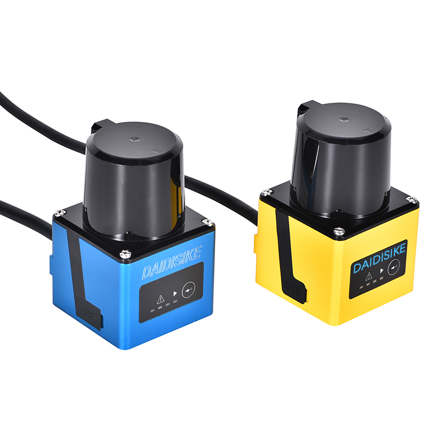
DLD05A3, DLD20A5, SDLD-05A and DLD30T-5N are non-safety sensing models. Their configurable detection zones do not become certified protective fields. The LiDAR range by safety and sensing duty separates them from ST27, the confirmed Type 3 / PL d / SIL 2 safety scanner. Check the exact interface and manual before specifying inputs, timing or a controller pairing. Record allowed fields, speeds and transitions using the ISO 3691-4 vehicle field-design guide.
References
- IEC 61496-3:2025 — Safety of machinery: electro-sensitive protective equipment, Part 3 (active opto-electronic protective devices responsive to diffuse reflection).
- ISO 13855:2024 — Positioning of safeguards with respect to the approach speeds of parts of the human body.
- ISO 13849-1 — Safety-related parts of control systems: general principles for design, Performance Levels.
- ISO 3691-4:2023 — Industrial trucks: safety requirements and verification for driverless industrial trucks and their systems.
- ANSI/A3 R15.08 — Industrial mobile robots: safety requirements.
Related reading
Industrial Safety LiDAR — Complete Reference
Pillar guide covering the full safety-scanner topic cluster.
Zone Configuration Basics
Primer on warning and protective fields and the teach-in process.
Safety Laser Scanner for Anti-Collision
Anti-collision applications and field-set patterns for factories.