
DX-D2 / DX-D3 Guard Door Interlock Switches
Tongue-operated, positive-break interlocks that tell your safety relay the guard is really closed — the straightforward, million-cycle way to monitor doors that do not need to be locked shut.
- Positive-break NC contacts: ≥60 N / ≥10 mm forced separation
- 4 contact codes, from 1NC+1NO up to 3NC
- Resin head; IP67 excluding the actuator-key opening
- −20 °C to +60 °C without freezing; humidity below 85% RH
- 8 key insertion directions, DX-K actuator range
- Designed to IEC/EN 60947-5-1 and GB 14048.5-2017
Current factory catalogue: DX-D2/D3 specifications and the four ordering codes on PDF page 5; key dimensions and installation on pages 6–8. Shared guard-locking headings in the catalogue do not give DX-D2/D3 a locking function.
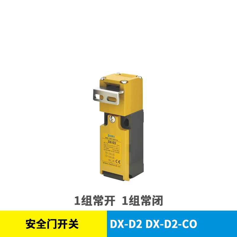
The Monitoring Tier of the DX Door-Lock Family
Not every guard needs to be locked. Where the machine risk assessment confirms that the hazard ceases before a person can reach it through an opened guard, the circuit may need a trustworthy door-closed signal, not a holding force. The DX-D2 and DX-D3 deliver exactly that: a stainless actuator key on the door enters the switch head, and withdrawing it mechanically forces the NC contacts open.
Because they omit the solenoid and lock segment of their DX-W siblings, these switches are the economical entry point of the DX range for position-monitoring tasks. Where the assessment demands guard locking, evaluate the exact variant and monitored release arrangement of the DX-W2/DX-W3 solenoid locks, the RFID-monitored DX-D6. A DXL door bolt can provide mechanical retention or a mounting arrangement, but pairing it with DX-D2/D3 does not create monitored safety guard locking or replace the required run-down hazard protection.
The D2 and D3 bodies share the same operating principle and resin head, with IP67 excluding the actuator-key opening; the published difference is contact capacity — DX-D2 carries two contacts (CO or 2C), DX-D3 carries three (2CO or 3C).
Positive-Break Operation, Illustrated
Original schematic, simplified — internal cam geometry is representative only, not a wiring diagram or proof of achieved safety performance. The controller, final switching elements and measured stopping behaviour must fulfil the required safety function; guard closure alone must not initiate hazardous motion.
Technical Specifications
Source: factory catalogue dated 2026-05-08, PDF page 5. The four listed ordering codes are the current standard supply range.
| Operating principle | Tongue/key-operated mechanical contacts (no locking segment) |
|---|---|
| Contact configurations | DX-D2-CO (1NC+1NO) / DX-D2-2C (2NC) / DX-D3-2CO (2NC+1NO) / DX-D3-3C (3NC) |
| Forced separation | Force ≥60 N; travel ≥10 mm, within documented conditions (not guard-holding force) |
| Rated insulation voltage Ui | 400 V |
| Conventional thermal current Ith | 8 A |
| Rated operating point Ue / Ie | AC 400 V / 2 A |
| Mechanical / electrical life | Over 1,000,000 mechanical / over 300,000 electrical operations under rated conditions |
| Head material & protection | Resin head; IP67 excluding the actuator-key opening |
| Key insertion | 8 directions; DX-K series actuator keys (preparation clearance 1-2.5 mm, slot tolerance ±1 mm) |
| Conduit entry | M20 in the selection table. The overview mentions a PG13.5 gland; confirm the supplied gland/adapter assembly. |
| Ambient temperature | −20 °C to +60 °C, without freezing |
| Ambient humidity | Below 85% RH |
| Operating frequency | Up to 20 operations per minute |
| Standards basis | Designed to IEC/EN 60947-5-1 and GB 14048.5-2017 (design and test reference standards); certification documents on request |
Choosing Between the Four Codes
| Ordering code | Contacts | NC contacts available | Status contact | Best for |
|---|---|---|---|---|
| DX-D2-CO | 1NC + 1NO | 1 | Yes | Basic interlock + door lamp/PLC bit |
| DX-D2-2C | 2NC | 2 | No | Two NC inputs, subject to controller compatibility and validation |
| DX-D3-2CO | 2NC + 1NO | 2 | Yes | Dual channel plus status feedback |
| DX-D3-3C | 3NC | 3 | No | Three NC contacts; circuit allocation requires validation |
NC contact count is not a safety category or Performance Level. Confirm the input wiring and diagnostics in the exact safety controller manual before selecting the circuit architecture.
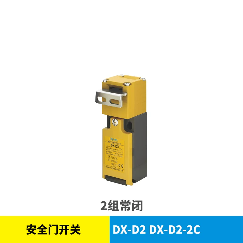
DX-D2-2C Variant
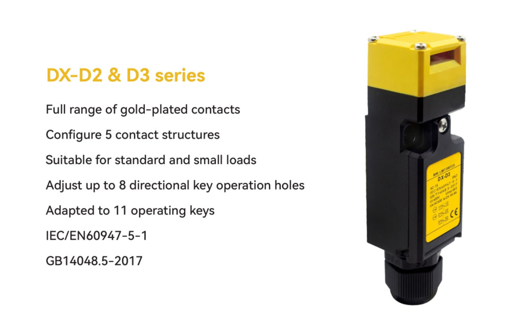
Series Features
Historical brochure illustration: the image below still says “5 contact structures”. It is not the current ordering list. Use the four standard codes in the table above: D2-CO, D2-2C, D3-2CO and D3-3C. Eight insertion directions and eleven actuator-key variants are separate selection dimensions.
Typical Applications
Machine-Tool Guard Doors
Monitor the enclosure door through a validated safety input circuit. Where the spindle can still be hazardous on access, use the required guard-locking and release function instead.
Inspection Hatches & Covers
Million-cycle mechanical life fits hatches that are opened every shift for cleaning or inspection.
Cost-Sensitive OEM Machines
The economical interlock tier of the DX family for circuits that need door detection but not door locking.
Coolant-Mist & Washdown Zones
IP67 excludes the actuator-key opening. Position and protect the switch so coolant, powder and cleaning jets cannot enter that opening; check the documented environmental conditions.
Bolt-Plus-Interlock Assemblies
Check the DXL bolt's model-specific mounting pattern for a mechanical bolt plus guard-position signal assembly. This does not provide monitored safety guard locking.
Legacy Interlock Replacement
NC/NO contacts can suit relay-based cabinets, subject to checking the actual terminal arrangement, ratings, input diagnostics and required safety function before replacement.
Frequently Asked Questions
What does positive break (forced separation) mean on the DX-D2/DX-D3, and why should I care?
Withdrawing the actuator key mechanically operates the NC contacts. The factory table lists forced-separation force ≥60 N and travel ≥10 mm; these are operating specifications, not door-holding ratings. Positive-opening behaviour applies within the documented mechanical and electrical conditions, not as a guarantee against every overload, damage or installation fault. The complete validated safety circuit must detect the door opening and bring the hazard to its required safe state.
Which of the four contact codes should I choose?
The current standard ordering list is DX-D2-CO (1NC+1NO), DX-D2-2C (2NC), DX-D3-2CO (2NC+1NO) and DX-D3-3C (3NC). D2 has two contacts per switch and D3 has three; four ordering configurations does not mean four contacts in one device. Select the NC/NO arrangement against the documented input circuit of the chosen safety relay or controller. Two NC contacts can serve a suitably validated dual-channel design; contact count alone does not establish a safety category, Performance Level or automatic compatibility with every controller.
Can the DX-D2/DX-D3 keep the door shut while the machine coasts down?
No — DX-D2/D3 monitors guard position and has no locking segment. If a person could reach a run-down hazard before it has ceased, select a suitable guard-locking device and validated lock-monitoring/release control, checking the exact DX-D6 or DX-W2/W3/W5 variant where appropriate. A DXL mechanical door bolt may provide a mounting or manual-retention arrangement, but adding it to DX-D2/D3 does not create monitored safety guard locking and is not a substitute for the locking safety function required by the risk assessment.
How do the 8 key insertion directions help during machine design?
The adjustable head provides up to eight key insertion directions. This is separate from the eleven actuator-key variants shown in the catalogue: DX-K1/K1D, K2/K2D, K3/K3D, K4/K4D, K5, K6 and K8. Choose the exact key and bracket for the door geometry, then follow the installation drawing, including the 1–2.5 mm preparation position and ±1 mm insertion alignment tolerance. The number of directions is not the number of supplied keys.
What are the electrical limits of the contacts?
Rated insulation voltage Ui 400 V, conventional thermal current Ith 8 A, rated operational point Ue AC 400 V / Ie 2 A. Treat the switch as a pilot device: route motor and heater loads through a safety relay or contactor, and let the DX-D2/D3 switch only the relay's input circuit. Electrical life is rated at 300,000 operations versus 1,000,000 mechanical.
Are these switches certified, and what standards do they follow?
The design follows IEC/EN 60947-5-1 and GB 14048.5-2017 (low-voltage switchgear, control-circuit devices and interlocks) — these are design and test reference standards. Certification documents are available on request; the safety performance actually achieved depends on your complete circuit, so validate at system level with the safety relay you deploy.
What should an export buyer confirm before ordering DX-D2/DX-D3?
Confirm the full ordering code against the four-model table, the separate DX-K actuator-key model and the cable-entry assembly. The current selection table specifies M20 conduit entry; the catalogue overview also mentions an included PG13.5 gland, so confirm the supplied gland/adapter arrangement rather than treating these thread designations as interchangeable. The published environment is −20 °C to +60 °C without freezing and below 85% RH. IP67 excludes the actuator-key opening: keep contaminants and cleaning jets out of that opening. Confirm quantity, lead time and OEM marking with the quotation.
PDF & 3D CAD Downloads
Browse all downloads3D CAD MODELS
Find the file for your exact model
Open the download center with the named series selected. Search your full model, check the file details and download the matching STEP file.
Confirm the document and CAD file match your exact ordered version before installation or mechanical design. Contact us if your model is not listed.
Author background: Engineer Cai, Senior Application Engineer. See certificates.
Safety Light Curtain — Customer Cases
Real installations from DAIDISIKE clients. Click any case to view in full. Filter by scenario to quickly find a similar setup.
Press Guarding · Safety Light Screen
Robot Cell · Safety Light Barrier
Anti-Interference · Adjacent Installations
Access Gate · Guarding Light Curtain
Workstation · Compact Light Screen
Packaging Line · Machine Safety Light Curtain
Large Opening · Multi-Beam Safety Device
Assembly Conveyor · Photoelectric Light Curtain
Detection · Safety Light Array (Measurement)
Area Guarding · Safety Light Grid