
DX-W2 Solenoid Guard Locking Switch
The workhorse safety door lock of the DX family: 1300 N of holding force, two monitoring compartments, and 14 contact configurations so the switch matches your circuit — not the other way around.
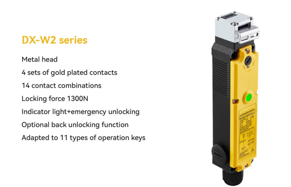
- 1300 N holding force; forced separation ≥80 N / ≥10 mm
- 4 contact blocks, 14 NC/NO codes, 28 catalog models
- GD (power-to-lock) and GC (power-to-unlock) versions
- 24 V DC 4.8 W solenoid; IP67; -20 °C to +60 °C
- Optional rear manual unlock kit (DX-W2-L)
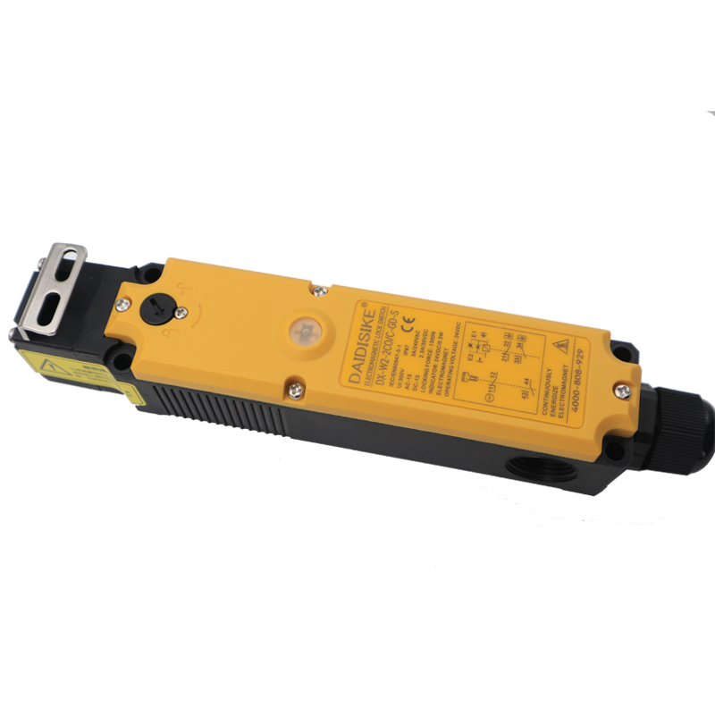
Built Around the Machine-Tool Door Upgrade
The most common safety retrofit we quote is the same story: a machining center or press whose guard door opens the instant the operator pulls it — while the spindle is still turning. A monitoring-only interlock cannot fix that. The DX-W2 adds the missing ingredient: guard locking. The actuator key on the door is captured by the switch head, a solenoid-controlled mechanism holds it with 1300 N, and the door only opens when the control circuit says the hazard has actually stopped.
What distinguishes the DX-W2 inside the family is its contact menu. Two independent compartments — one watching the actuator (door) position, one watching the lock state — carry four contact blocks in 14 NC/NO combinations. Dual-channel door monitoring plus lock feedback plus HMI status can all come from one device, wired straight into a DQSRN or DA31 safety relay. Need fewer contacts? Step down to the DX-W3. Need more? The DX-W5 carries six blocks. Need RFID coding and 2000 N? That is the DX-D6.
The Guard-Locking Cycle in a Safety Circuit
Original schematic. Release timing (step 3) is produced by your control system — standstill monitor, safe timer or safety PLC — not by the door lock itself.
Technical Specifications
| Holding force | 1300 N |
|---|---|
| Contact system | 4 blocks in 2 independent compartments (actuator side / lock side); 14 NC/NO configurations; gold-plated silver-alloy contacts |
| Locking versions | GD = electromagnetic locking, mechanical release; GC = mechanical locking, electromagnetic release |
| Solenoid supply | 24 V DC ±10 %, 4.8 W (approx. 200 mA) |
| Contact ratings | AC-15 240 V / 3 A; DC-13 30 V / 2.3 A |
| Mechanical / electrical life | 1,000,000 / 150,000 operations |
| Forced separation (manual override) | ≥80 N over ≥10 mm |
| Housing | IP67; J = metal head / S = plastic head (body material: contact factory) |
| Cable interface | G = M20 conduit entry (unwired) / X = factory-fitted 1.5 m cable |
| Operating temperature | -20 °C to +60 °C |
| Actuator keys | DX-K series, 11 models; door radius R > 300 mm, positioning tolerance ±1 mm |
| Accessory | DX-W2-L rear manual unlock kit (sleeve per panel thickness, limit plate, 3× M4 screws, 90°-turn metal knob) |
| Certification note | Certification documents available on request; achieved PL/Category depends on the complete circuit design |
Contact-Code Quick Reference
Code format: DX-W2-[actuator side]/[lock side]-[GD|GC]-[J|S], where C = 1 NC, O = 1 NO (e.g. 2CO = 2 NC + 1 NO). All 14 combinations below are available in both GD and GC:
| Actuator / lock code | Door-side contacts | Lock-side contacts |
|---|---|---|
| CO/CO | 1NC + 1NO | 1NC + 1NO |
| CO/2C | 1NC + 1NO | 2NC |
| 2C/CO | 2NC | 1NC + 1NO |
| 2C/2C | 2NC | 2NC |
| C2O/C | 1NC + 2NO | 1NC |
| 3C/C | 3NC | 1NC |
| 2CO/C | 2NC + 1NO | 1NC |
| C/3C | 1NC | 3NC |
| C/C2O | 1NC | 1NC + 2NO |
| C/2CO | 1NC | 2NC + 1NO |
| O/3C | 1NO | 3NC |
| O/2CO | 1NO | 2NC + 1NO |
| 2C/2O | 2NC | 2NO |
| 2O/2C | 2NO | 2NC |
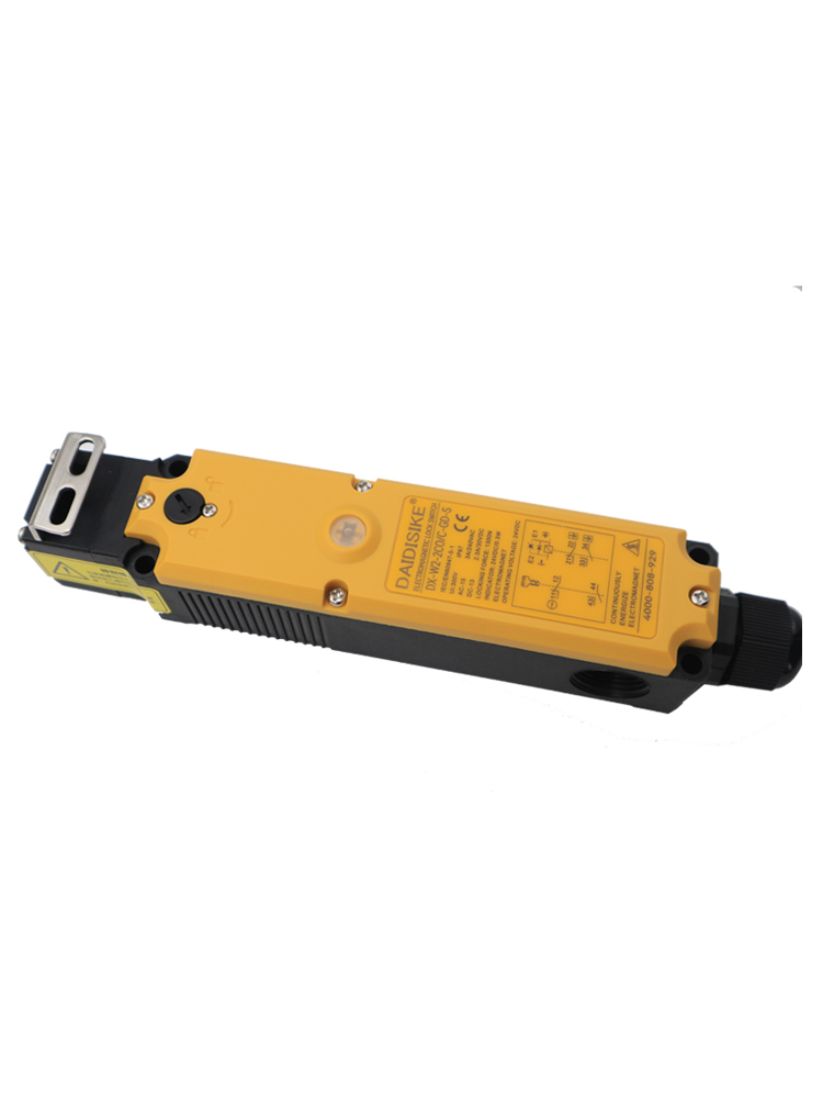
Product Views
Series Features
Head Rotation & Rear Unlock Installation
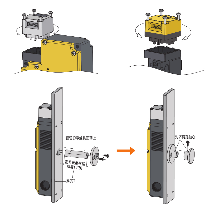
The head can be re-oriented so the key enters from the direction your door actually approaches, and the DX-W2-L sleeve passes through the guard panel (length matched to panel thickness) to put a mechanical release knob on the inside of the cell.
Typical Applications
CNC Spindle Coast-Down Doors
1300 N holds the guard while the spindle runs down; door + lock NC channels prove both states to the relay.
Injection & Die-Casting Gates
IP67 body and gold-plated contacts survive oil mist and frequent cycling on molding-shop gates.
Machine-Tool Safety Retrofits
Contact-based output drops into existing relay cabinets — no electronic safety bus needed on legacy machines.
Robot Cell Maintenance Doors
Order a code with spare NO contacts for HMI lock-status display alongside the dual safety channels.
Press & Stamping Enclosures
Locked guarding for tools with stored energy; ≥80 N/10 mm forced separation keeps an escape path.
Cells Needing Inside-Release
DX-W2-L rear unlock kit gives personnel inside the cell a mechanical way out.
Frequently Asked Questions
My machine keeps spinning after the stop button — how does the DX-W2 handle coast-down?
The lock and the door signal are separated. When the operator requests entry, the control system first brings the hazard to a standstill (timer or standstill monitor), and only then energises or de-energises the solenoid to release the 1300 N lock. Until that release, pulling on the door achieves nothing — the door-monitoring contacts stay closed and the guard stays shut. This is the core of a machine-tool safety door upgrade: the door can no longer be opened into a coasting spindle.
GD or GC — which locking logic should my risk assessment pick?
GD is electromagnetically locked and mechanically released: losing solenoid power releases the lock, so it suits machines where a power cut also removes the hazard quickly. GC is mechanically locked and electromagnetically released: the lock holds through a power failure and needs the solenoid energised to open, suiting hazards that persist after power loss (thermal, coasting, stored energy). All 14 contact codes exist in both versions, so the electrical design does not constrain this choice.
How do I read a code like DX-W2-2C/CO-GD-J?
The part before the slash is the actuator (door position) compartment, the part after is the lock-status compartment: C = one NC, O = one NO, so 2C/CO means two NC contacts monitoring the door plus one NC and one NO monitoring the lock. Then GD/GC is the locking logic, and the final letter is the head/interface: J = metal head with M20 conduit entry, with S (plastic head) and X (factory-fitted 1.5 m cable) variants available under the same structure.
Which contacts go to the safety relay and which to the PLC?
Wire the NC pairs — typically door-monitoring NC plus lock-monitoring NC — into the dual-channel input of a DQSRN or DA31 safety relay, so the machine can only run when the door is both closed and locked. Use the NO contacts for PLC status: door-open indication, lock-state display, or interlock diagnostics on the HMI. With 14 combinations you can order exactly the mix your I/O plan needs instead of adding auxiliary relays.
Can a trapped operator or a power failure leave the door permanently locked?
No. Independent of the solenoid, the mechanism supports forced separation at ≥80 N over ≥10 mm as a manual override. In addition, the optional DX-W2-L kit adds a rear unlock knob (90° clockwise turn) on the inside of the guard — specify it whenever someone could plausibly be inside the cell when the door closes. On GD versions, cutting solenoid power also releases the lock.
How does the DX-W2 differ from the DX-W3, DX-W5 and DX-D6?
Same platform, different contact counts and technologies: the DX-W3 is the compact 2-contact-block version, the DX-W5 carries 6 contact blocks for status-rich cells, and the DX-W2 sits in the middle with 4 blocks but the widest choice — 14 configurations. The DX-D6 moves to RFID-coded electronic monitoring with 2000 N holding force. If you are consolidating an order, all mechanical models share the DX-K actuator key range.
What environmental and lifetime figures apply?
IP67 sealing, -20 °C to +60 °C operating range, gold-plated contacts, 1,000,000 mechanical operations and 150,000 electrical (contact-switching) operations. Contact ratings are AC-15 240 V/3 A and DC-13 30 V/2.3 A — pilot duty for relay inputs, not motor loads. The housing material is not separately published; request it from the factory if your specification calls it out.
What should I confirm before placing an export order for the DX-W2?
The full order code (contact configuration / GD or GC / head and cable interface), the DX-K key model per door, whether the DX-W2-L rear unlock kit is needed (specify guard panel thickness for the sleeve), and quantities for pricing. Small trial orders are generally workable; certification documents are available on request. Contact the factory for current MOQ and lead time.
PDF & 3D CAD Downloads
Browse all downloads3D CAD MODELS
Find the file for your exact model
Open the download center with the named series selected. Search your full model, check the file details and download the matching STEP file.
Confirm the document and CAD file match your exact ordered version before installation or mechanical design. Contact us if your model is not listed.
Specs reviewed by Engineer Cai, Senior Application Engineer. See certificates.
Safety Light Curtain — Customer Cases
Real installations from DAIDISIKE clients. Click any case to view in full. Filter by scenario to quickly find a similar setup.
Press Guarding · Safety Light Screen
Robot Cell · Safety Light Barrier
Anti-Interference · Adjacent Installations
Access Gate · Guarding Light Curtain
Workstation · Compact Light Screen
Packaging Line · Machine Safety Light Curtain
Large Opening · Multi-Beam Safety Device
Assembly Conveyor · Photoelectric Light Curtain
Detection · Safety Light Array (Measurement)
Area Guarding · Safety Light Grid