

The inquiry: “what lock for a door that meets in the middle?”
The example considers a CNC work-envelope guard that is not a single hinged panel but a double-leaf, bi-parting door: two sheet-metal leaves that slide apart and meet at a central stile. The question was simple and fair: “What kind of safety door lock should we buy for this double door?”
The central meeting stile allows two independent access paths. A correctly designed pair of interlocks can monitor them separately; this is not inherently unsafe. If the design instead uses one bolt and one lock, validate that neither leaf can open or create an accessible gap while the lock reports engaged. Door flex, mounting looseness and opening order must be included in that check.
Two standards, two jobs: ISO 14120 for the door, ISO 14119 for the lock
Before choosing hardware it helps to split the problem the way the standards do. ISO 14120:2015 governs the guard itself — the sheet-metal door and its structure — and it explicitly excludes interlocking devices, handing those to ISO 14119. So on this machine the double door is the ISO 14120 movable guard, and the bolt-and-switch hardware bolted to it is the ISO 14119 interlock. ISO 14119:2024 (the current edition, superseding 2013) is the Type-B2 standard for the design and selection of interlocking devices associated with guards, including guard-locking devices. Preventing unexpected start-up is the job of ISO 14118, while the stop function's performance level / SIL and architecture come from ISO 13849-1 and IEC 62061. Keeping those lanes straight is what stops a conversation about “a door lock” turning into guesswork.
The solution: a DXL-B safety door bolt + a DX-W2 guard-locking switch
Make the two leaves into one closure with a sliding safety door bolt, then lock and monitor that single closure with a guard-locking switch. The components considered are a DXL-B bolt and a selected DX-W2 guard lock. The pictured DX-W2-2020C-GD-S is a product reference, not evidence that an order was shipped or the proposed machine was validated. A sliding bolt that ties the inactive leaf of a door pair at the meeting stile is the same idea as a flush bolt or astragal in building hardware — a well-established mechanical concept.
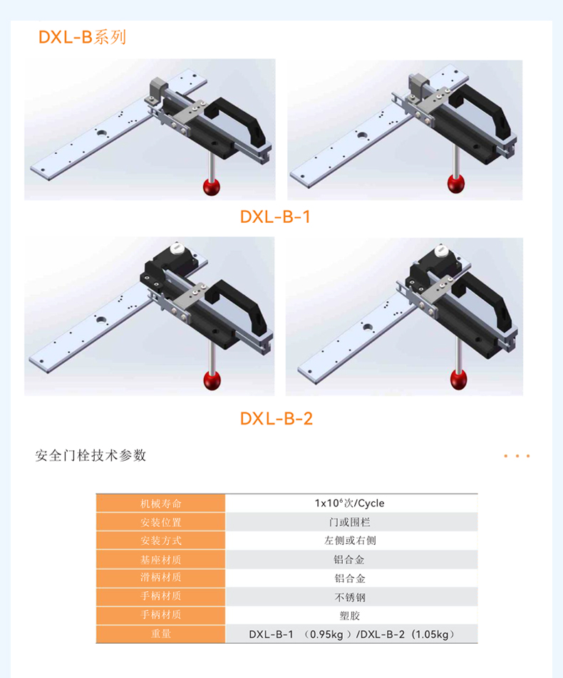
The detail that makes this one designed system rather than two parts taped together: the DXL-B base is pre-drilled with mounting holes for the DAIDISIKE DX-W2 / DX-D2 / DX-D3 / DX-W3 safety switches. The bolt is purpose-built to carry a guard-locking/interlock switch. In the proposed arrangement the bolt actuator enters the lock. Check actuator compatibility, anchorage and clearances, then prove neither leaf can create an accessible gap while the lock reports engaged. Pre-drilled holes simplify mechanical mounting; they do not establish safe retention or monitoring.
Why a plain interlock wasn't enough: access time vs run-down time
Guard locking is required when the access time is shorter than the machine's stopping (run-down) time. That is the core selection rule, and it's a comparison of two times. Access time is how long it takes a person to reach the hazard once the guard starts to open. Stopping time is how long the dangerous motion actually takes to coast to a halt after a stop command. Measure the actual CNC spindle/axis stopping behaviour and shortest access path. If a person can reach a persisting hazard, a position-only interlock does not provide the required retention. Select a documented guard-locking and release function; the CNC label alone does not prove a particular DX-W2 variant is suitable.
Power-to-lock vs power-to-release: which principle, and why it matters
Two locking principles exist and you must choose deliberately so the name matches the action. Spring-applied / energise-to-release (also called power-to-release): power releases the lock, and a spring drives it to the LOCKED state when power is removed, so on a power failure the door stays locked. This fail-locked, closed-circuit behaviour is the principle ISO 14119 favours for protecting people. Energise-to-lock (power-to-lock): power must be present to keep it locked, so on a power failure the spring releases and the door can be opened — a fail-unlocked, open-circuit principle generally used for process protection, and requires an explicit loss-of-power and escape assessment for any personnel-protection role. The DX-W2 “GD” designation is the power-to-lock (energise-to-lock) family, so confirm the fail-state your risk assessment requires before you pick the variant.
Power-to-lock needs an explicit loss-of-power assessment. A run-down timer or standstill monitor can control a normal unlock command, but cannot maintain electromagnetic retention when its power is lost. If the hazard persists through that failure, this variant alone does not establish personnel guard locking. Select an appropriate documented retention architecture, and evaluate escape and emergency-release needs before approving the installation.
Holding force, defeat resistance and the actuator type
Holding force. Choose the rated holding force (FZh) to withstand the static and foreseeable dynamic forces a person could apply to the locked guard. ISO 14119 distinguishes the rated holding force from the actuating and impact forces, so size it from your risk assessment. The DX-W2 family is rated holding force up to 1300 N; the pictured GD-S product label states 1000 N — a lower-force member of the family, not the same figure expressed two ways. Pick the member whose rated holding force meets or exceeds what your assessment needs; verify the applicable force definition and current manual rather than treating the pictured unit as a commissioned installation.
Defeat resistance. ISO 14119 defines four actuator types — Type 1 uncoded mechanical, Type 2 coded mechanical (a tongue or cam shaped to resist easy field tools like a screwdriver or ruler), Type 3 uncoded non-contact, Type 4 coded non-contact (RFID or magnetic) — and asks designers to minimise reasonably foreseeable defeat, by coding and by mounting so the device cannot be easily reached, removed or substituted. A tongue/bolt-actuated guard-locking switch like the DX-W2 is a mechanically actuated interlock (ISO 14119 Type 1 or Type 2 depending on whether the actuator is coded — confirm the coding level on the DX-W2 datasheet for your variant). On this door, the practical defeat resistance comes from the bolt geometry and from mounting the bolt and switch where they can't be casually reached — conceal and locate, don't rely on a clever trick.
How the bolt and switch combine: the close-to-run sequence
A proposed close-to-run sequence must be validated for the actual two-leaf installation:
- Both leaves closed → the operator slides the DXL-B bolt across the meeting stile, tying leaf-to-leaf and leaf-to-frame.
- The bolt's tongue/actuator enters the DX-W2.
- The selected lock must retain the bolt and both leaves under the assessed conditions; verify the lock-engaged safety signal and accessible gaps.
- The documented safety release function must prevent access until the relevant hazard has ceased; also validate power-loss and escape behaviour.
- The documented safety design must implement required output monitoring and restart prevention; re-closing the door alone must not start motion.
Wiring it: verify DX-W2 monitoring, controller compatibility and restart
Use the exact lock manual to distinguish guard-position and lock-engaged safety contacts from ordinary status signals. A documented safety controller must implement the required stop, release conditions and restart interlock. The DA31 specification does not establish EDM, monitored reset or a standstill/delayed-unlock function; obtain an applicable approved solution where these are required. Use the selected DX-W2 unit’s actual supply and AC-15/DC-13 contact ratings.
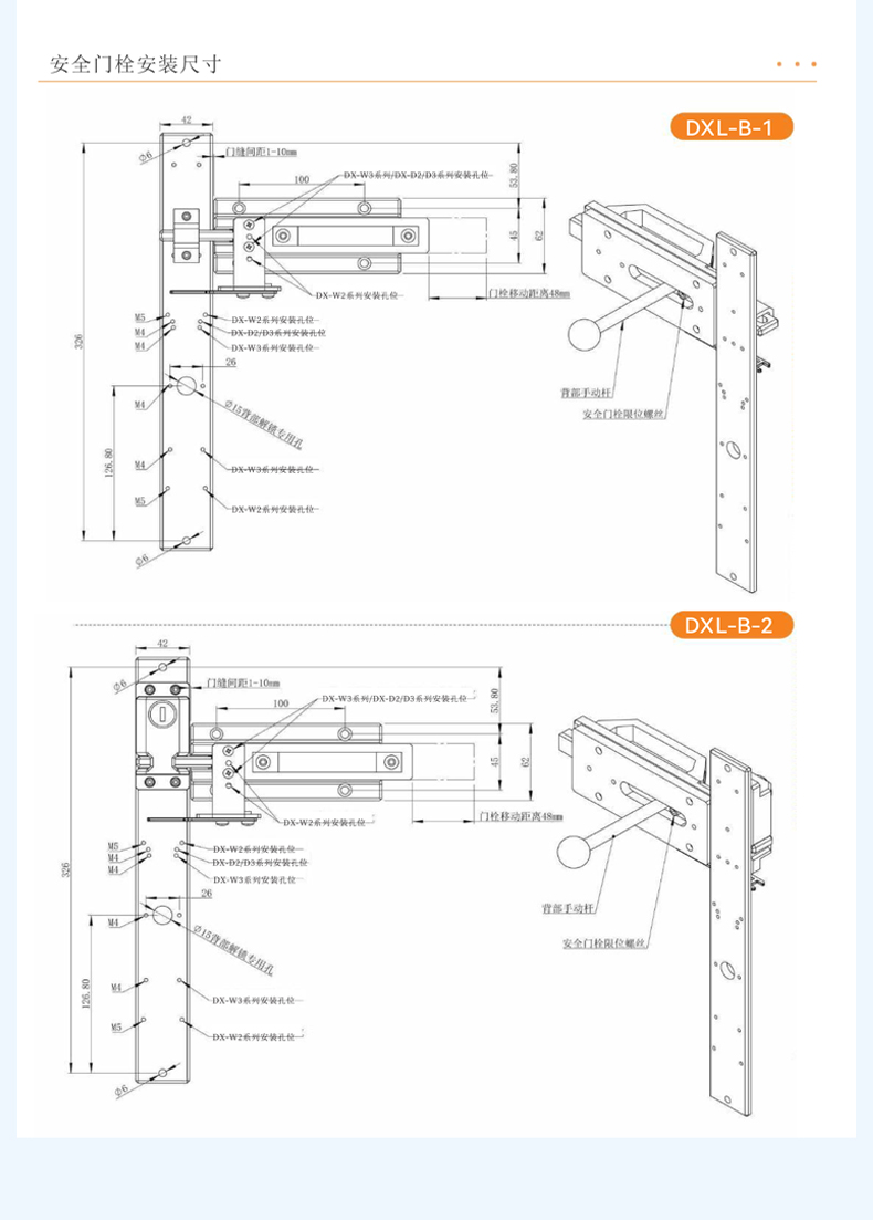
DXL-B safety door bolt — specifications
| Parameter | DXL-B series (DXL-B-1 / DXL-B-2) |
|---|---|
| Function | Sliding safety door bolt; ties two leaves (and frame) into one closure and presents the actuator to the safety switch |
| Switch compatibility | Base pre-drilled for DX-W2 / DX-D2 / DX-D3 / DX-W3 safety switches |
| Mechanical life | 1 × 10⁶ cycles |
| Door-gap range | 1–10 mm |
| Bolt travel | 48 mm |
| Base plate | ~42 mm wide × ~326 mm long |
| Materials | Aluminium-alloy base & slide-bar; stainless steel + plastic handle |
| Weight | DXL-B-1 0.95 kg / DXL-B-2 1.05 kg |
| Mounting | On a door or fence/guard, left or right side; rear manual rod / limit screw included |
DX-W2 guard-locking switch — specifications
| Parameter | DX-W2 (unit: DX-W2-2020C-GD-S) |
|---|---|
| Type | Mechanical interlock and electromagnetic guard locking; verify exact actuator type/coding |
| Holding force | Up to 1300 N (the GD-S unit here rated 1000 N) |
| Locking principle | “GD” = power-to-lock family |
| Standard | IEC/EN 60947-5-1 (GB 14048.5) |
| Rated insulation voltage | Ui 500 V |
| Utilisation category | AC-15 / DC-13 |
| Electromagnet | 24 VDC |
| Contacts | Gold-plated silver contacts |
| Protection | IP67; status indicator on unit |
Selection & install notes (and how it compares)
A short checklist for anyone facing the same bi-parting safety door:
- Confirm overrun. Measure or obtain the spindle/axis run-down time and compare it to the access time. If the hazard can be reached before a safe state, select a documented guard-locking design.
- Validate both access paths. Assess a properly anchored bolt arrangement or separate monitoring. Confirm DXL-B variant, 1–10 mm drawing gap, mounting side and retention geometry.
- Match holding force to the risk assessment — up to 1300 N available; the GD-S here is 1000 N.
- Decide the locking principle — power-to-lock (GD) only within a design that also resolves loss of locking power, or a power-to-release variant if your assessment calls for fail-locked.
- Verify the controller manual and restart design. DA31 EDM/monitored-reset capability is not established here; re-closing must not start the CNC.
If you're cross-shopping, a Schmersal AZM201 or an Allen-Bradley (Guardmaster) 440G guard-locking switch does the same job class; the DX-W2 is built to the same IEC 60947-5-1 device family with electromagnetic guard locking up to 1300 N. The practical advantage on a double door is that the DXL-B is pre-drilled to carry the DX-W2, so bolt and switch ship as a mounting candidate; confirm available combinations and quantity in the current quote. For the wider interlock range, see our Euchner / Schmersal interlock alternatives and the industrial safety door lock category. To get the mounting position right, run a fresh ISO 13855 safety-distance calculation for your machine.
The outcome
The described DXL-B/DX-W2 arrangement is an application narrative, not an independent commissioning certificate. Acceptance requires evidence that either leaf cannot expose the hazard while locked, safe release waits for the relevant hazard to cease, loss of locking power has the required outcome, and re-closing or reset cannot start motion. Retain actual test results, the exact supplied variant and the approved schematic before describing a specific installation as validated.