
Light Barrier (Safety Light Curtain): Working Principle, Types & Machine Guarding Guide
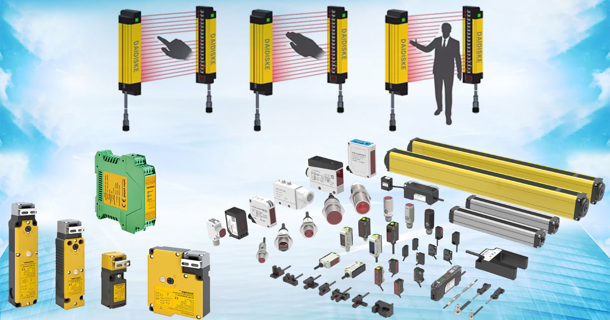
First, an introduction: how Type 2 and Type 4 safety levels are classified
IEC 61496 Type describes protective-device requirements; ISO 13849 Category and Performance Level describe different aspects of a safety control system. They are not interchangeable labels, and housing width or the number of visible connector pins cannot establish a rating.
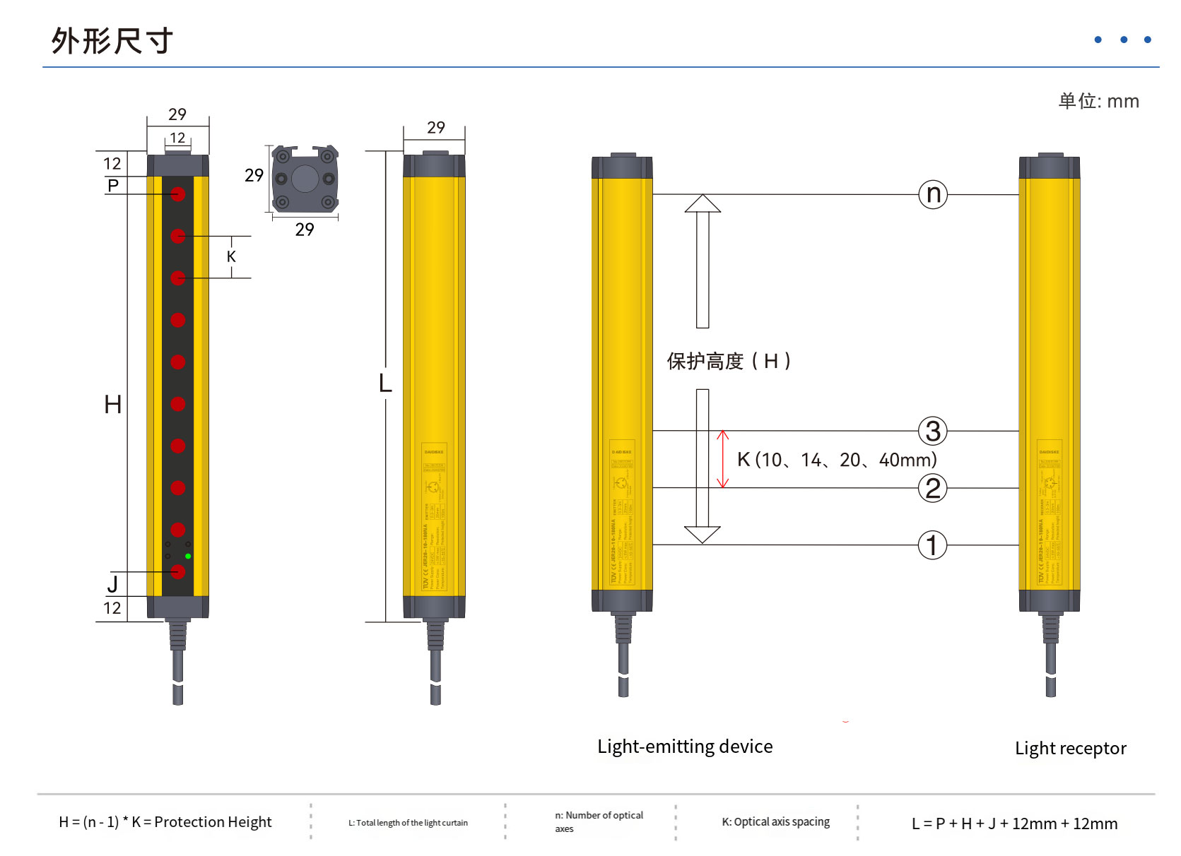
Type 2 and Type 4 AOPD light curtains have different test and fault-response requirements. Type 2 does not mean an untested single output is safe to wire directly to an ordinary PLC. Use the exact documented safety interface with an appropriate safety evaluator. The safety light-curtain selection rangeseparates model options from the application decision. On any unit, including the JER series, check the dimensioned protective field and housing end margins; do not infer classification or effective height from the illustration.
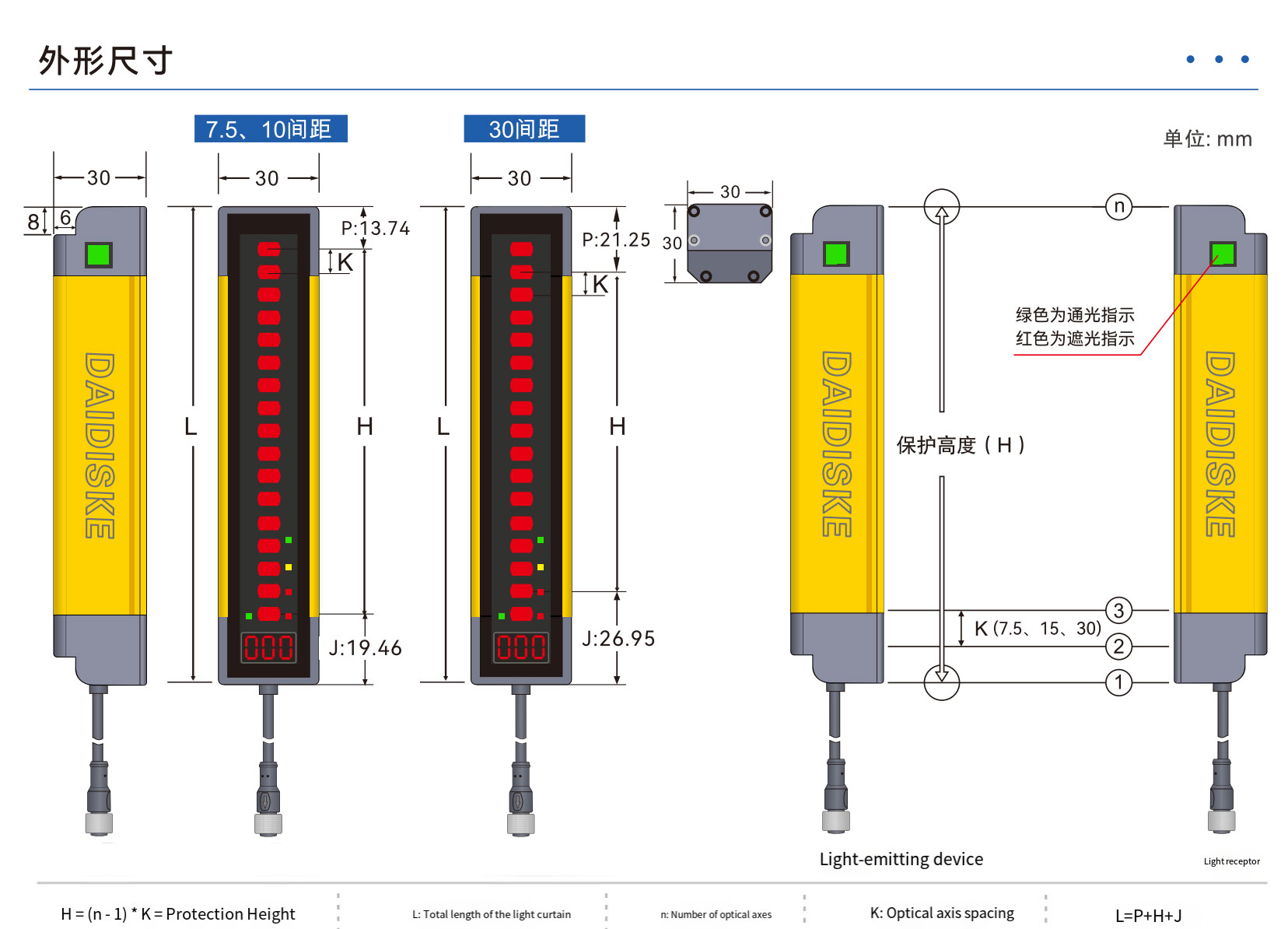
The DQT4 seriesis catalogued as Type 4. Its rating does not mean that every machine opening is covered or that all mechanical end zones disappear. Verify the actual protected height, mounting arrangement, required safety performance and model documentation.
Second, how a safety light curtain works: from infrared emission to a millisecond stop (response time)
A light curtain’s protective capability comes from its ‘emit - receive - control’ closed-loop system. The underlying mechanism can be broken down into the following key stages:
- Infrared beam matrix: a matched transmitter and receiver establish a defined detection field. Wavelength, beam arrangement and optical synchronization are product-specific; nominal beam pitch is not automatically the certified detectable object size.
- Signal verification: the receiver evaluates the expected beam signals and the device's diagnostics. Supported coding and interference controls depend on the model; no curtain is universally immune to sunlight, reflections or another transmitter.
- Intrusion detection: an object meeting the documented detection capability interrupts the field. Use the maximum response time for the selected configuration, not an invented microsecond processing value.
- Safety response: the approved safety output or communication interface signals the safety controller. The final switching devices and machine then reach the required safe state. Total stopping time includes the entire chain; a sensor cannot promise a universal press braking time or instantaneous removal of every hazard.
- Reset and recovery: clearing the field does not prove the safeguarded space is empty. Apply the required restart interlock and deliberate reset arrangement with visibility and access controls. Reset must not itself initiate hazardous motion.
Third, the core types of safety light curtain
Light curtains are categorised by safety level and protection requirements:
- By safety level (IEC 61496 standard), there are two main types:
- Type 2: periodic test and fault-response requirements apply. Select only where its documented safety capability meets the required function; low purchase cost or a conveyor label does not establish suitability.
- Type 4: more demanding fault-detection and fault-response requirements apply. This is not a promise that every component is duplicated or a universal self-test interval. Determine the required Type/PL/SIL from the assessment and applicable machine standard.
- By detection capability (resolution)
- Finger detection: a documented small test-object size, for example 14 mm on a suitable model, can support a finger-access design. Verify that capability independently of beam pitch.
- Hand detection: select the documented capability and the corresponding distance case. Values such as 25 or 30 mm are not interchangeable with finer finger detection.
- Body/access detection: coarse or multiple-beam systems require a specific access layout to prevent stepping over or crawling under. Do not use a coarse field for close hand access or assume a vehicle-mounted curtain is a validated collision-avoidance system.
- Based on the environmental flexibility
- Ingress protection: verify the exact model's IP rating, temperature limits and approved cleaning method. IP65, IP67 or IP68 does not itself establish resistance to chemicals, food washdown or oil.
- Ambient light: check specified illumination limits and permitted shielding or coding. No universal 100,000 lux outdoor capability is claimed here.
Fourth, machine-guarding applications: from stamping to logistics, covering the whole industry
- Metal processing: a suitable light curtain can detect access to a press, shear or other stoppable hazard, but only where the machine-specific assessment permits this safeguard and the hazard reaches a safe state before access. It does not contain ejected workpieces or make an unsuitable press stoppable.
- Robot cells and conveyors: distinguish crossing detection from someone remaining inside. A curtain does not inherently distinguish people from material. Material passage may require a separately assessed, supported and validated muting system with anti-entry measures. AGV safeguarding has additional vehicle-specific requirements and must not be inferred from this stationary example.
Fifth, selection and installation guide: avoiding common misconceptions
- Selection of core parameters
- Protective height: dimension the actual field against every access route, including over, under, around and through the opening. Overall housing length is not the protected height.
- Operating range: select a documented minimum and maximum range for the exact model, including approved mirrors or covers and environmental limitations. More range is not automatically better protection.
- Response time: use the worst-case configured sensor time plus all safety-control and machine delays. Do not choose a universal 10 ms threshold by machine category.
- Evidence: request exact-model safety ratings, declaration, applicable test or approval documents and installation manual. CE marking and the name of a testing organization do not alone establish Type, PL or SIL.
- Installation Key Points
- Alignment: use the manufacturer's alignment procedure and secure mounting. Verify detection with the prescribed test object; a signal-strength indicator alone is not acceptance.
- Safety distance: use the applicable ISO 13855 approach case and complete stopping time, including required intrusion and reach allowances. The approach speed is human approach, not the machine's maximum travel speed.
- Interference layout: respect reflective clearances and permitted transmitter arrangements. Use coding or shielding only if supported by the exact manual, and repeat the detection test.
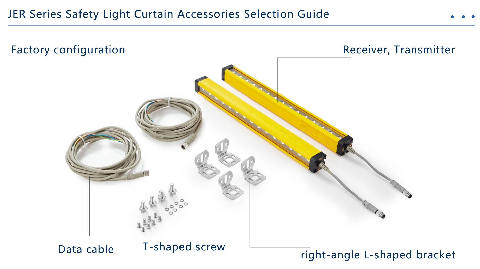
VI. Typical Troubleshooting and Maintenance Specifications
- Troubleshooting
- Unexpected stop: secure the machine and investigate contamination, alignment, reflection, supply and cabling using the diagnostic procedure. Do not enable blanking, muting or a material exemption to suppress an unexplained safety fault.
- Beam interruption: check for a real obstruction before alignment or supply checks. Use the exact specified supply, not a generic 12–30 V assumption.
- Safety-output fault: stop use and have a qualified person follow the model's fault procedure. Never bridge channels, force PLC inputs or bypass the evaluator to restore production.
- Maintenance Recommendations
- Clean at the interval justified by the environment and manual, using approved materials. Recheck the prescribed test object after cleaning.
- Test at commissioning, after relevant changes and at the documented inspection interval. For test-object sweeps, keep hazardous functions disabled and check the full specified path and boundaries. Perform stopping tests only under a controlled, qualified validation procedure.
- Record faults, corrective action, configuration and inspection results. Damaged wiring or unresolved failures are a hold point; do not restart until protection has been restored and checked.
VII. Conclusion: technology-based safety, efficiency and balancing protection
A light curtain can provide access detection without a movable fence at that opening, but it is only one element of machine protection. Retain fixed guarding for bypass routes and hazards such as ejection. Select the documented model and safety-control design, validate stopping distance and restart prevention, and maintain the resulting protection. The examples above describe application questions, not verified customer installations or guaranteed performance.
Sources and application limits
IEC 61496-1:2020 and IEC 61496-2:2020define device requirements; ISO 13855:2024addresses positioning. The SICK deTec4 Core manualillustrates model-specific mounting, safety integration and test requirements. Read the manual for the installed device; do not transfer its options to a different model.