
How to Select the Right Safety Light Curtain
Content updated:
This article focuses on dimensional and distance checks within the machine-safety standards framework; use the series and application comparison for the procurement shortlist. ISO 13855:2024 addresses positioning, not automatic approval of a particular series.
I. Define Your Core Requirements
To avoid incorrect model selection, first determine the primary application of the safety light curtain:
- Equipment Safety Protection: Ideal for hydraulic presses, punch machines, and automated production lines to prevent limbs or workpieces from entering hazardous zones.
- Hazardous Area Perimeter: Designed for safeguarding fixed or mobile danger zones, such as the operating radius of robotic arms.
- Detection & Measurement: counting or dimensional measurement is a process function; an ordinary measuring grating cannot substitute for a certified protective curtain.
- Specialized Environments: check the exact environmental and optical limits. An immersion rating alone does not validate underwater person protection or high-pressure cleaning.
II. Key Parameters and Model Identification
1. Definition of Core Parameters
- Effective Protection Height (H): Must cover the entire hazardous opening of the equipment (e.g., the distance from the upper mold to the lower mold).
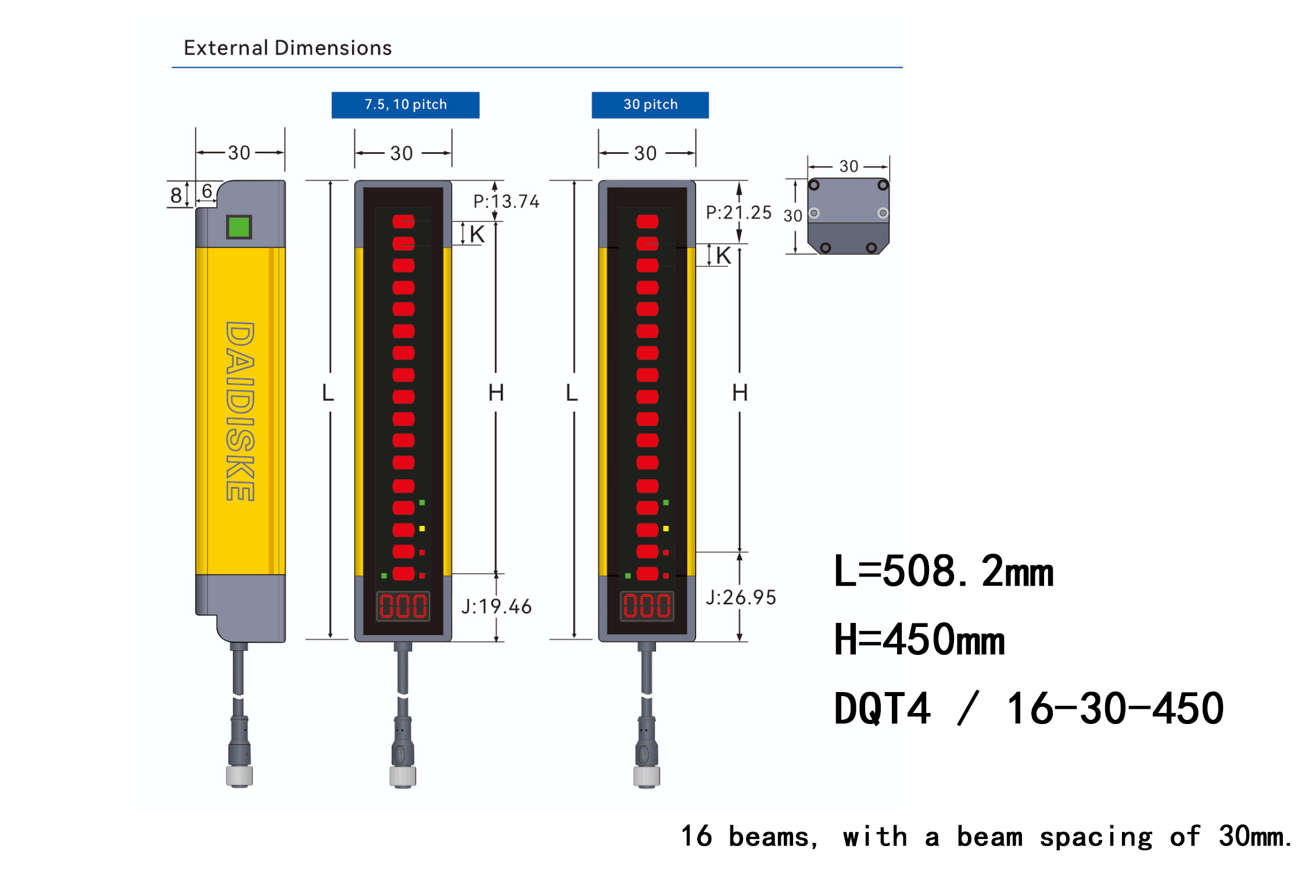
- Total Height (L): The actual physical height of the grating, including the top and bottom housing.
- Optical Axis Pitch (K): The distance between adjacent optical axes. Use this pitch in the catalogue dimensional formula only; verify the declared detection capability separately. It is not universally equal to pitch.
2. Safety Distance Calculation
Model selection must comply with international standard EN ISO 13855.
Historical reach-through illustration: S = K × T + C; not the complete ISO 13855:2024 method
Illustrative hand-detection calculation: assume a documented 30 mm detection capability, a total T = 0.5 s including all sensor, safety-logic and stopping delays, and the conventional perpendicular-approach method. C = 8 × (30 − 14) = 128 mm gives an initial 2000 × 0.5 + 128 = 1128 mm. Where that method permits the 1600 mm/s recalculation above 500 mm, the result is 1600 × 0.5 + 128 = 928 mm. Check reaching-over, other access routes and machine-specific requirements before accepting the final distance; this does not establish a universally safe hydraulic-press layout.
III. Case Study
Hydraulic Press Protection — illustrative dimensional check:
For the model notation DQT4/16-30-450, 16 beams at a 30 mm pitch give a 450 mm catalogue beam span. Confirm the exact ordered model, active field, declared detection capability and mounting drawing. This example is not a verified customer result, and the height calculation alone does not establish safe guarding.