
How to Calculate Safety Light Curtain Minimum Distance (ISO 13855)
Content updated:
Calculation boundary: the worked example below illustrates the conventional perpendicular-approach hand-detection calculation; it is not a complete assessment for every ESPE geometry. Begin with the machine-safety standards framework, then confirm the applicable ISO 13855:2024 method, machine-specific requirements and reaching-over/under/around access before accepting a distance.
Buying a top-tier safety light curtain is only half the battle. If you mount the sensor too close to the hazard, a worker's hand could still reach the dangerous area before the machine completely stops. That makes the entire investment useless.
To prevent this, international standards like ISO 13855 dictate exactly how far away your sensors need to be. Let's cut through the dense engineering jargon and look at how to actually calculate this minimum safety distance for your factory floor.
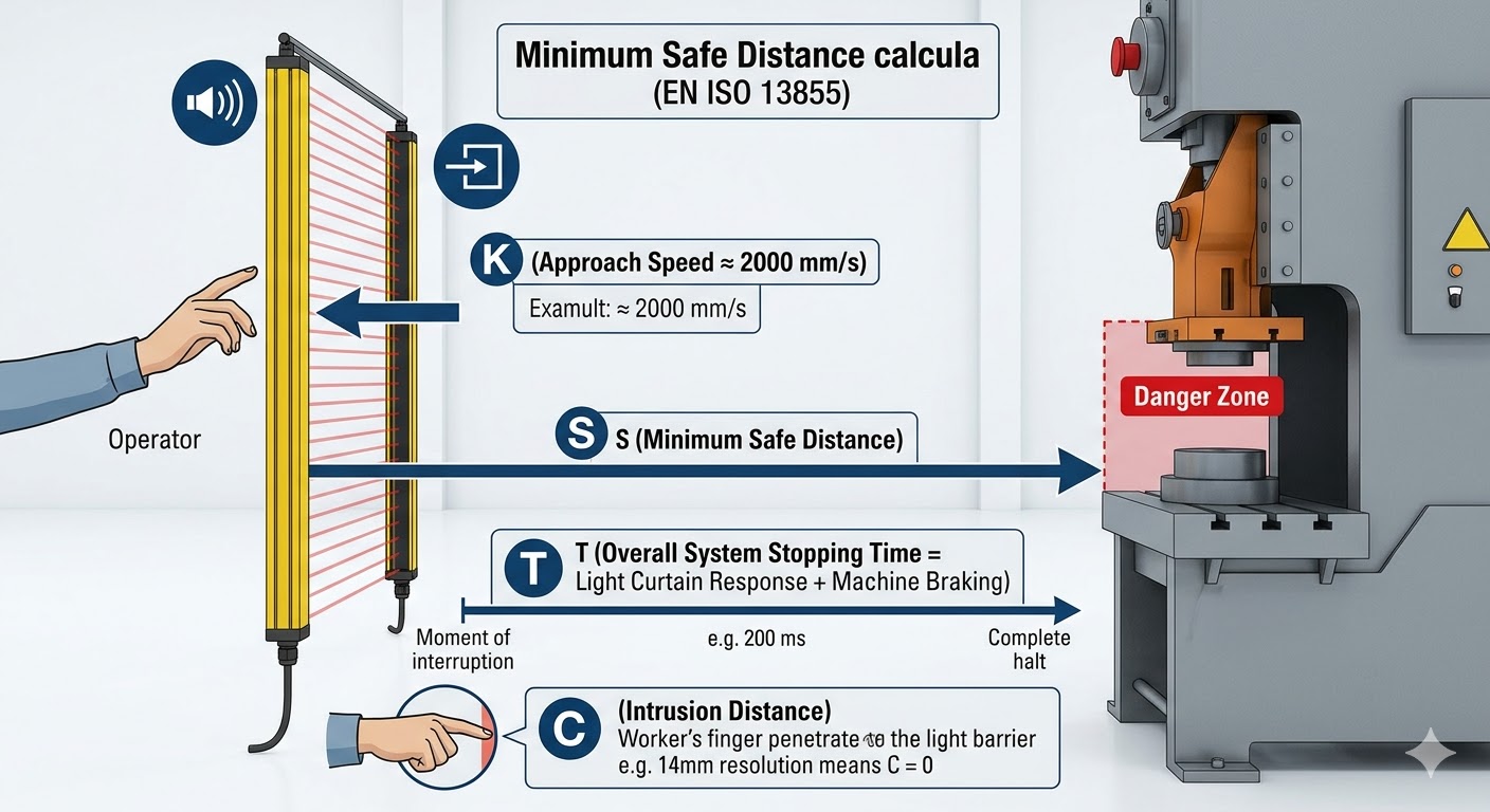
The ISO 13855 Formula Explained
The following historical perpendicular reach-through arithmetic illustrates S = K × T + C for a fine-resolution curtain. It is not the complete ISO 13855:2024 method. The calculated example must be checked against all relevant reach, geometry and uncertainty allowances before selecting the installed distance.
Here is what you are actually measuring:
- S (Minimum Safe Distance): The final distance from the light barrier to the hazard (measured in mm).
- K (Approach Speed): use the value prescribed for the applicable approach. In the conventional perpendicular hand-detection method, calculate first at 2000 mm/s; if the result exceeds 500 mm, the permitted 1600 mm/s recalculation must not result in less than 500 mm. Do not choose 1600 merely because someone can walk toward the machine.
- T (Total Stopping Time): This is crucial. It is NOT just the machine's braking time. It is the sensor's response time + the qualified safety logic's processing time + the machine's mechanical stopping time (measured in seconds).
- C (Intrusion Distance): An extra safety buffer depending on the sensor's resolution. If the infrared beams are further apart, a finger might slip through before being detected, meaning you need a larger ‘C’ value.
A Real-World Calculation Example
For a hypothetical press that is suitable for presence-sensing safeguarding, assume the following measured/documented inputs. These are teaching values, not a DAIDISIKE product specification or a measured customer installation:
- You install a DAIDISIKE high-resolution safety light curtain with a 14 mm resolution (perfect for finger protection).
- The light curtain reacts in 0.015 seconds (15 ms).
- The press machine and relays take 0.150 seconds (150 ms) to completely halt.
Step 1: Find the Total Stopping Time (T)
Add the times together: 0.015 s + 0.150 s = 0.165 seconds.
Step 2: Find the Intrusion Distance (C)
For the conventional perpendicular hand-detection example with 14 mm ≤ d ≤ 40 mm, use C = 8 × (d − 14). Since we are using a precise 14 mm sensor, our math is simple: 8 × (14 − 14) = 0 mm.
Step 3: Calculate the Final Distance (S)
Assuming the fast hand approach speed (2000 mm/s):
S = (2000 × 0.165) + 0 = 330 mm
Example result: 330 mm is the arithmetic result for these stated inputs. Accept it only after checking the applicable minimum, reach-over/under/around allowances, the full stopping-time measurement and machine-specific safeguarding requirements. Mount no closer than the final validated distance.
Why Sensor Resolution Can Save Factory Space
A finer documented detection capability can reduce the reach-through intrusion term in this example. It does not remove reaching-over or other positioning requirements, so a 14 mm device does not automatically permit closer mounting than a 30 mm device in the final layout. Compare the complete applicable calculation before claiming a floor-space benefit.
When in doubt, don't guess. Machine braking times degrade as equipment ages, and regulatory bodies don't accept rough estimates. If you are unsure about which resolution fits your workflow or how to wire the setup correctly, the engineering team at DAIDISIKE can help prepare the model data for your qualified integrator's assessment and validation.
For the example's conventional calculation, see the SICK C4000 Select manual. It is a device-specific legacy reference, not a replacement for the current standard. In the US, OSHA's mechanical-press guidance excludes presence-sensing protection on full-revolution clutch presses.