
DQO Blind Spot-Free Series Safety Light Curtain Wiring Guide: Standard Connection Method for Dual-Side 7-Core Cable
Content updated:
For the DQO dual-side 7-core arrangement, identify the exact ordered output variant and use its supplied terminal drawing before energising. The colour map below is a guide to that arrangement, not a universal connector pinout. Both protective channels must be evaluated by compatible qualified safety logic; compact end coverage does not remove the need to assess reaching around the field.
The safety installation and wiring guide explains the complete protective circuit and commissioning checks. Compare the exact DQO model and drawing with this article before connecting power, CP or CE.
How Does a Safety Light Curtain Work?
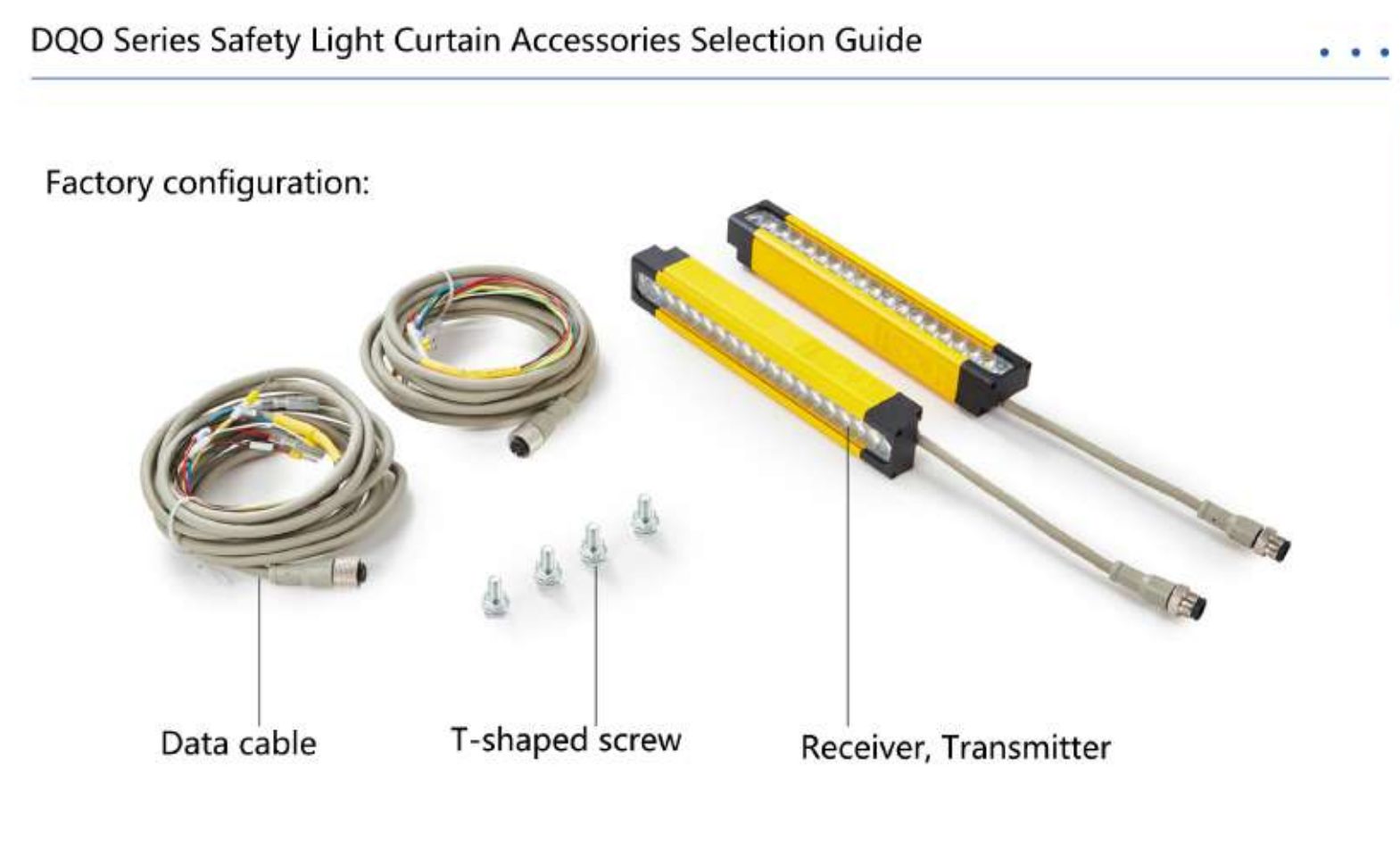
I. DQO Series 7-Core Cable Color Definitions (Pin Definitions)
The DQO series utilizes a highly flexible 7-core aviation cable. Compared to standard 5-core cables, it offers richer signal interactions (such as dual OSSD outputs or enhanced synchronization signals).
| Cable Color | Signal Definition | Function Description |
|---|---|---|
| Brown | +12~24VDC | Power Positive |
| Blue | 0V / GND | Power Negative |
| Black | CP (Control Signal) | Synchronization signal line between transmitter and receiver |
| White | OSSD 1 | Safety Output Signal 1 (Connects to safety relay) |
| Green | OSSD 2 | Second protective channel; evaluated together with OSSD 1 by compatible safety logic |
| Red | CE (Communication Enhancement) | Variant-specific CE function: verify the supplied drawing; do not assume EDM or reset |
| Yellow/Gray | GND/Shield line | Shield/ground designation in this arrangement; terminate only as the exact wiring and EMC instructions specify |
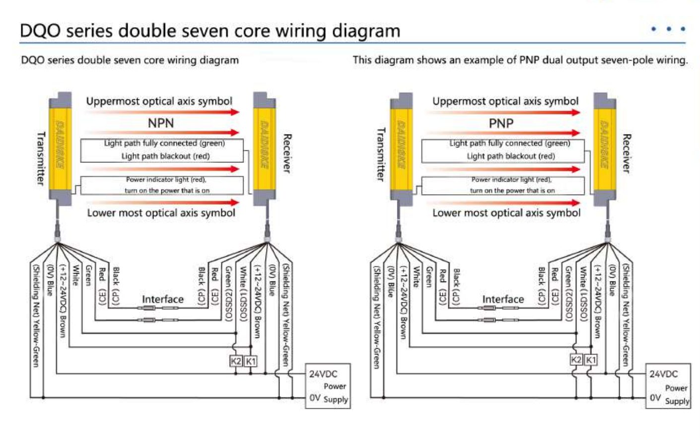
II. DQO Series Dual-Side 7-Pin Standard Wiring Diagram Analysis
The following colour convention concerns the depicted dual-output arrangement. Confirm its NPN/PNP variant, output behavior and safety-input compatibility from the exact order-code documentation; dual wiring alone is not proof of standards compliance:
1. Transmitter Wiring Steps
- Power Connection: Brown wire to 24VDC, blue wire to 0V.
- Synchronization Connection: For the depicted arrangement, CP connects the specified transmitter and receiver terminals. Confirm the supplied drawing; synchronization does not itself establish end-to-end protective coverage.
- Auxiliary Signal: Verify CE against the exact supplied diagram. Do not connect it as generic self-test, EDM or reset feedback.
2. Receiver Wiring Steps
- Dual-Channel Output: Connect both the white wire (OSSD 1) and green wire (OSSD 2) simultaneously to the input terminals of a safety relay or safety PLC. Use the compatible safety-input configuration and validated protective stop function; this is not an emergency-stop pushbutton circuit.
- Status Indication: The DQO series features built-in segmented indicator lights. When wired correctly, the receiver displays real-time feedback based on the status of the light beam.
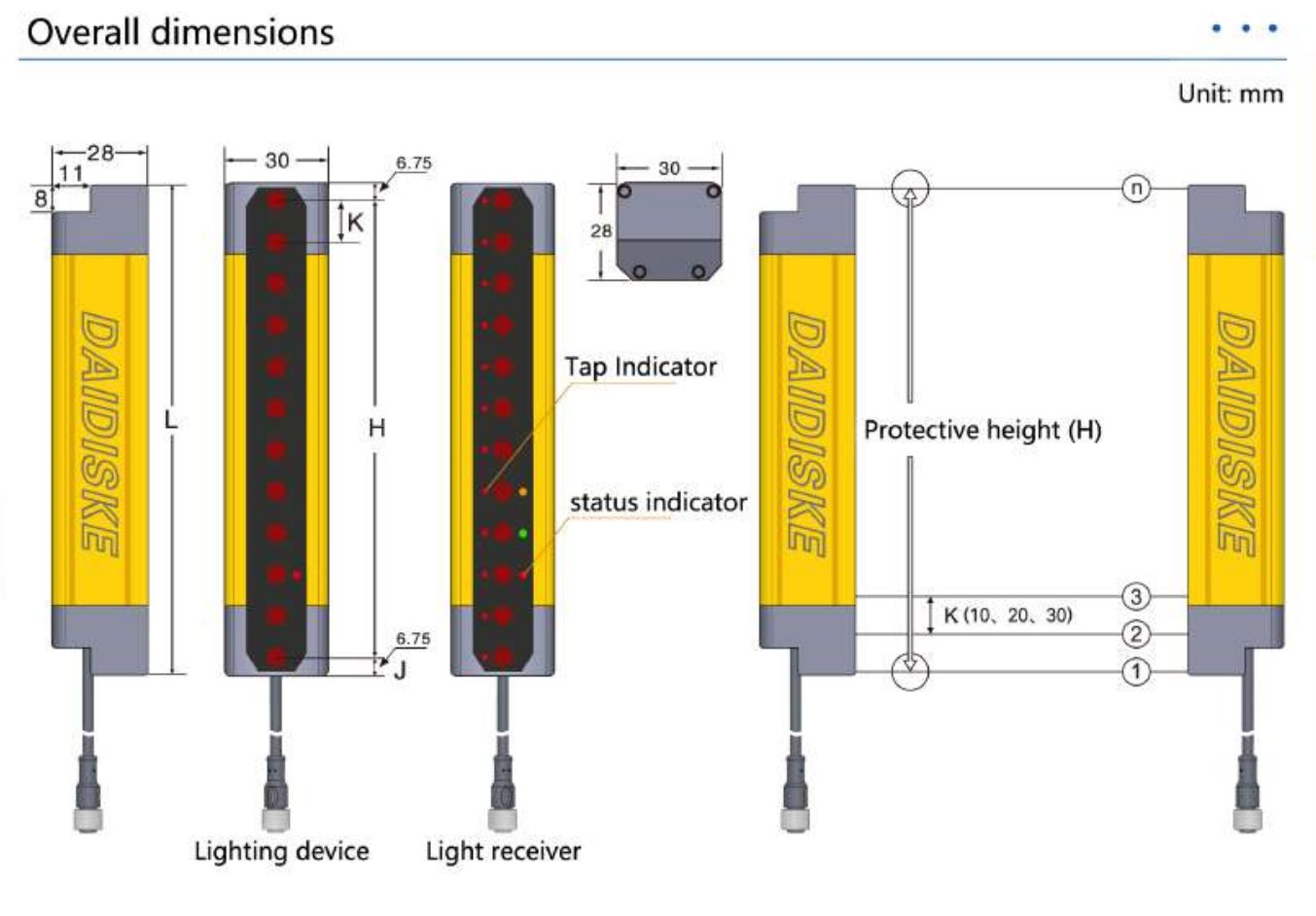
III. Core Advantages of the DQO Series: No Blind Zone Monitoring
The “No Blind Zone Series” designation stems from the DQO series' optimized ratio between housing and optical lens:
- End-to-End Sensing: Check the active-field endpoints on the exact dimensional drawing. The series designation does not prove that every housing, bracket and cable opening is guarded.
- Response time: The product page lists ≤15 ms, which is 0.015 seconds, not 0.01 seconds. Use the documented worst-case time for the exact model in the complete stopping-time calculation.
- Detection capability: Confirm the smallest detectable object specified for the exact order code. Catalogue 10/20/30 mm pitch options must not be labelled finger, palm or arm protection solely from spacing.
IV. Installation and Commissioning Recommendations
- Shield and bonding: Follow the equipment-specific EMC and protective-bonding instructions for cable shielding and termination. Core count does not establish a universal shield connection.
- Optical Axis Alignment: Use the DQO's built-in status indicator lights for alignment commissioning. When all optical axes are clear, the indicator turns green; if any axis is blocked or wiring is faulty, it displays red.
- Selection Notes: Select the active protective height from the exact model table, not housing length alone, and check all access paths, mounting clearance and total stopping distance.
V. Summary
The DAIDISIKE DQO Series Safety Light Curtain uses a compact end-coverage design whose protective field must be verified against the installed opening. During wiring, ensure the independence of the OSSD dual-channel outputs to maximize safety effectiveness.
If you encounter indicator flashing or signal inconsistencies during DQO series commissioning, please check your wiring against this guide or contact DAIDISIKE technical support for immediate assistance.