
Power Press Safety Upgrade: Installing Safety Light Curtains & Servo Feed Systems
Upgrading a press and its material feed is one coordinated engineering project, but it contains two different decisions. The press feeding and coil-handling equipment range addresses decoiling, straightening and controlled stock advance. The press photoelectric protection guide addresses whether an optical safeguard is suitable for the machine at all. This is a planning example, not a verified customer accident report or a claim of measured production improvement.
Content updated: 2026-09-06.
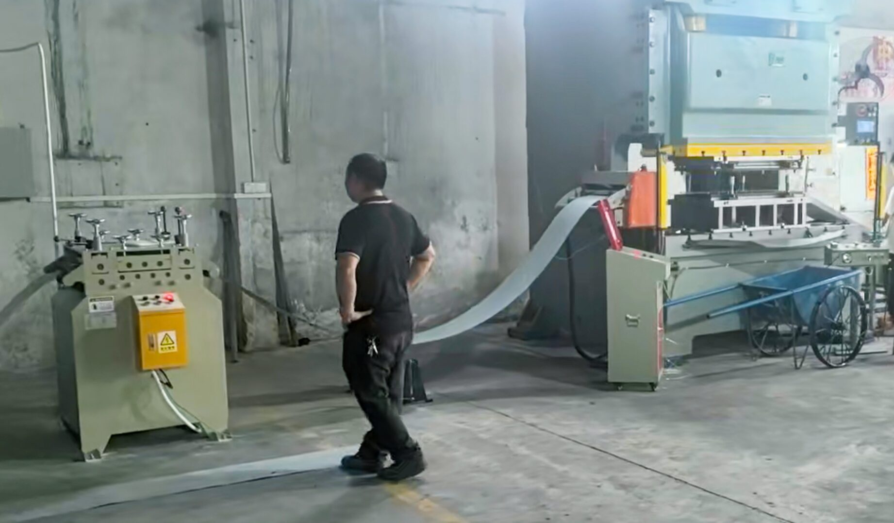
01 Why Guard a Mechanical Power Press — And Why Now
The die area can cause severe crushing or amputation injuries. Safeguarding must match the press type and task, including setting, feeding, clearing jams and maintenance. A light curtain issues a stop demand; it cannot create braking capability or stop the slide instantaneously. Under OSHA 1910.217, presence-sensing point-of-operation devices are prohibited on full-revolution-clutch mechanical power presses within that rule's scope. A part-revolution machine still needs a validated control and braking system.
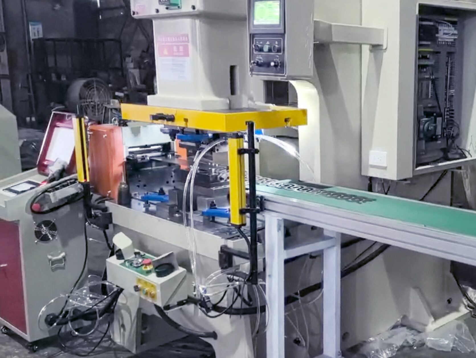
02 Safety Light Curtain: Your First Line of Defense
The DQS press guard uses an emitter, receiver and matched controller. The current product catalogue describes dual relay dry-contact outputs, not a universal pair of PNP OSSDs. Check the ordered controller variant, approved wiring, contact monitoring and restart behavior before selecting a receiving safety controller. Never infer compatibility from the product family name.
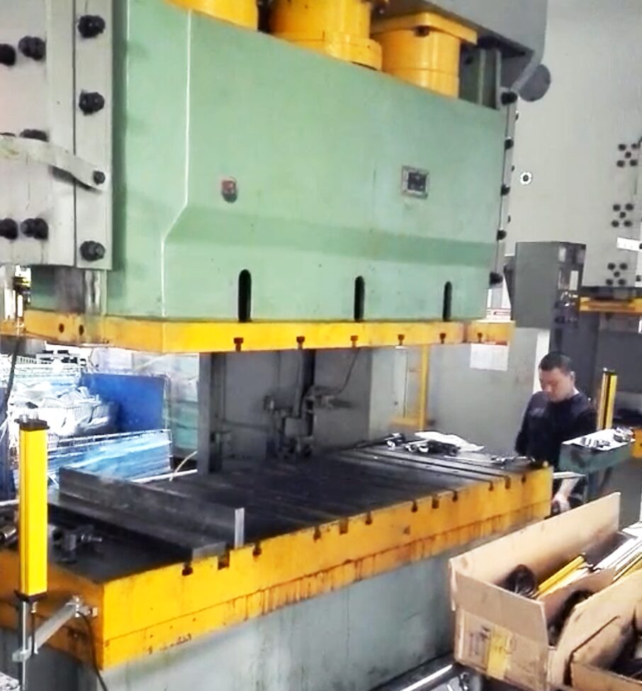
03 Install & Commission the Light Curtain the Right Way
Model selection
Determine the required safety performance from the press-specific risk assessment and applicable rules. Type 4, Category 4 and PL e are different concepts: a device type or a component rating does not establish the achieved performance of the complete circuit. Choose detection capability for the body part and access geometry, protected height for the opening, and an interface documented for both connected devices.
Safety distance (S = K × T + C)
Use this relationship only as an introduction to the applicable ISO 13855:2024 method. K and the required additional distances depend on the approach and arrangement; C is not an arbitrary structural allowance. T must cover the full worst-case detection-to-hazard-stop chain. Record which delays a measured stopping time already includes, then add only missing stages. Check reaching over or around the field and a person standing behind it as separate access problems.
Step-by-step installation
- Confirm eligibility. Establish the press type and stopping capability before approving optical safeguarding.
- Cover access. Locate the field at the calculated distance and prevent reaching around, below or over it; address whole-body presence behind it.
- Fit and align. Follow the exact mounting and reflective-surface clearances in the device manual. Do not use an arbitrary tilt angle as a reflection remedy.
- Validate the interface. Use the documented controller variant, pinout, supply, cable routing and safety input circuit. A connector that fits proves none of these.
- Test under controlled conditions. With hazardous motion prevented, pass the specified test piece through the entire protected field, including its boundaries. Separate stopping-time and fault tests require an approved method, safe observation and recorded acceptance criteria.
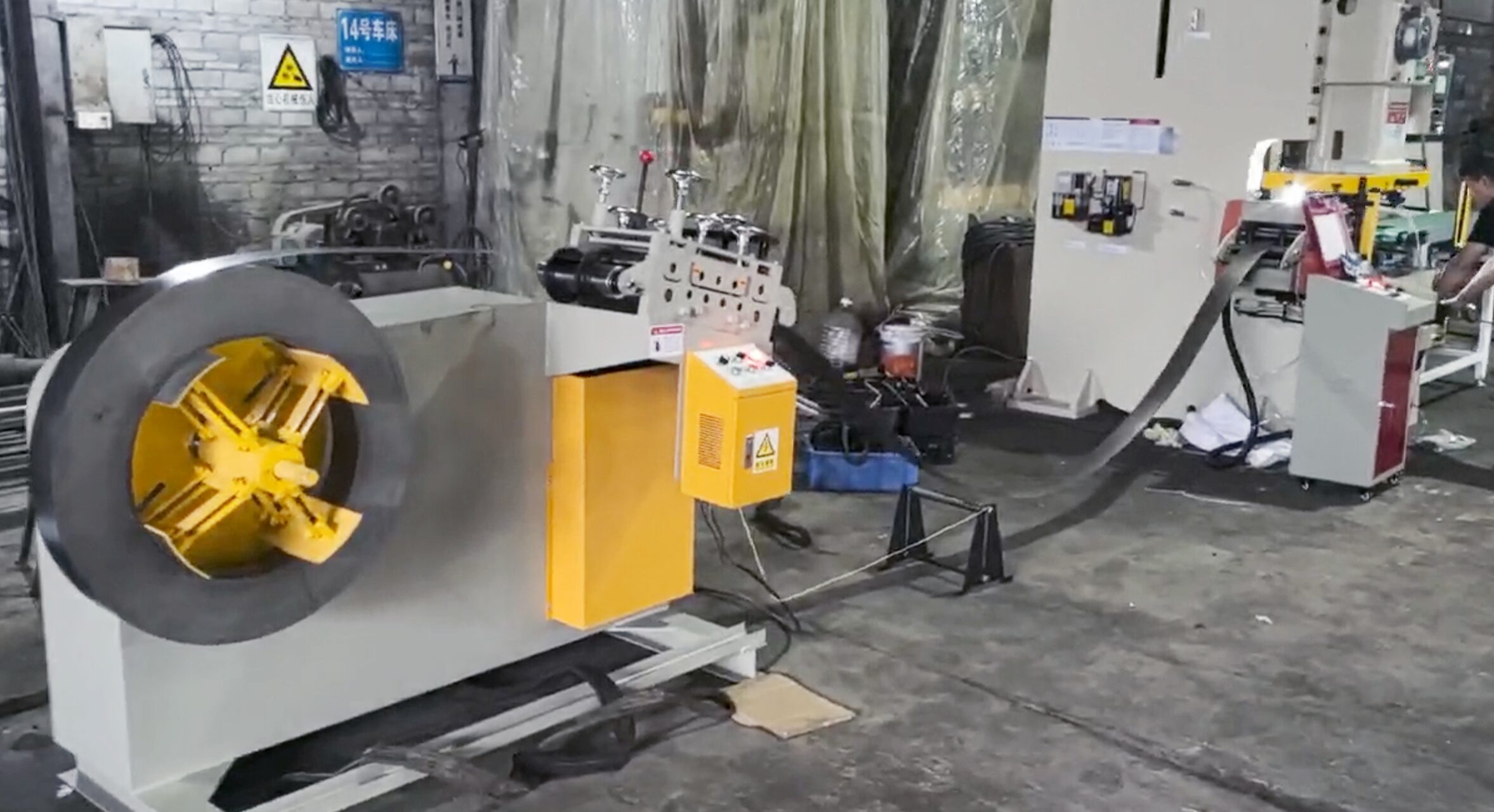
04 Integrating a 2-in-1 Decoiler–Straightener & an NC Servo Feeder
A 2-in-1 decoiler–straightener combines two stock-handling stages; an NC servo roller feeder then advances the programmed length. Specify coil mass and dimensions, stock width, thickness and strength, straightening requirement, feed length, cycle demand and available loop space before choosing a model. Roller hardness, material capacity, achievable speed and feed accuracy must come from the ordered equipment's documentation and acceptance tests, not a generic retrofit example.
NC servo feeder setup
- Stock path: match the approved die and feeder centerline, support the strip and assess sharp edges, whip and loop access.
- Guides and rollers: use the model's stock-specific settings and tolerances. Adjust, clean or unjam only under the required isolation and stored-energy procedure.
- Threading: define a safeguarded setup mode and access arrangement for reels and pinch points; do not reach between powered rollers to correct tracking.
- Cycle handshake: validate feed-ready, feed-complete, press-position and fault sequencing for production. If position or stopping is safety-related, use the required safety-rated implementation rather than an ordinary controller bit.
05 System Integration & Safety Optimization
DQS catalogue dry contacts must connect to a compatible, documented safety evaluation circuit; do not label them OSSDs or substitute a standard PLC input for the protective stop. The complete press and feeder safety design must specify which hazards stop together, final-element monitoring where required, and a reset that cannot initiate unexpected motion. A separate auxiliary status signal can inform the HMI; it is not the stop channel.
06 Common Issues and Safe Diagnostic Boundaries
- Optical faults: take the affected protective function out of service, inspect contamination, mounting and reflections under safe conditions, and use only manufacturer-approved remedies. Never blank a beam to hide a fault.
- Feed inaccuracy: isolate before checking guides, rollers and height alignment; compare results against the agreed stock-specific tolerance, not a generic clearance or accuracy claim.
- Missing protective stop: prevent use immediately. A competent person must diagnose and revalidate the full sensing, logic and stopping chain before return to service; alignment alone is not acceptance.
Wrap-up
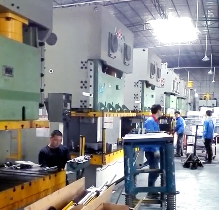
The press and coil-handling application footage can help discuss visible layouts. It cannot replace the exact model, circuit and validation records required below.
Release the upgraded line only when both workstreams close: the press safeguarding validation and the feeder's mechanical, control and production acceptance. Keep the risk assessment, ordered-device documents, stopping-time measurements, access checks, circuit drawings, restart tests and operator procedures together. No injury-free period or productivity improvement is claimed for the illustrative layout in this article.