
Not Every Punch Press Can Be Fitted with a Safety Light Curtain (ESPE)
Whether a light curtain can be added depends on the press’s actuation/braking design and its ability to stop. This page gives screening criteria and evidence requirements, not an approval for a particular machine.
Read this first
Quick decision: a part-revolution clutch and brake can make a press a candidate for optical safeguarding, but no drive type is automatically suitable as-is. Verify worst-case stopping performance, safety control reliability, all access paths and restart prevention before approving the retrofit.
Not suitable as-is: a full-revolution clutch that cannot stop the hazardous stroke. Under OSHA 1910.217, presence-sensing point-of-operation devices are prohibited on those mechanical power presses within its scope. Select an appropriate guarding arrangement or consider a professionally engineered machine replacement or major conversion. A two-hand control is not a universal workaround for a non-stoppable press.
The press photoelectric protection range helps identify candidate devices after that eligibility decision. It does not certify the existing clutch, brake or control circuit.
Standards reference: IEC/EN 61496 (ESPE/safety light curtains), ISO 13849-1 (safety control PL), ISO 13855 (location of safeguards).
Why can’t all presses use a light curtain?
A light curtain is a presence-sensing safeguard: when hands or objects cross the protective field, the safety control system must command the required stop so that hazardous motion ends before the person reaches the hazard point. If the machine cannot stop mid-stroke (e.g., a full-revolution crank once engaged must complete the cycle), then even if the curtain detects intrusion it cannot prevent the press from continuing. A stop signal is therefore insufficient to provide the required protection at that opening.
Compatibility matrix (simplified)
| Press type | Light curtain as-is? | Notes | Typical alternative/retrofit |
|---|---|---|---|
| Mechanical with part-revolution clutch and brake | Candidate, not automatic approval | Demonstrate reliable stopping and the required safety control and brake monitoring. | Validate the device interface, full stopping time, separation distance and all access paths. |
| Mechanical with non-stoppable full-revolution clutch | No presence-sensing point-of-operation retrofit as-is | The hazardous stroke continues despite detection; OSHA prohibition applies within its scope. | Assess suitable guarding or an engineered machine replacement/major conversion, not merely a sensor addition. |
| Pneumatic, hydraulic or servo press | Conditional | The drive label does not establish safe stopping or holding against stored energy and gravity. | Validate the actual valve, brake, drive and monitoring arrangement for every hazardous motion. |
| Mechanical press described only as having a clutch and monitored brake | Insufficient information | Identify clutch type, permitted operating modes and the actual safety control architecture. | Obtain manufacturer documents and measured stopping evidence before choosing a safeguard. |
Recommended model
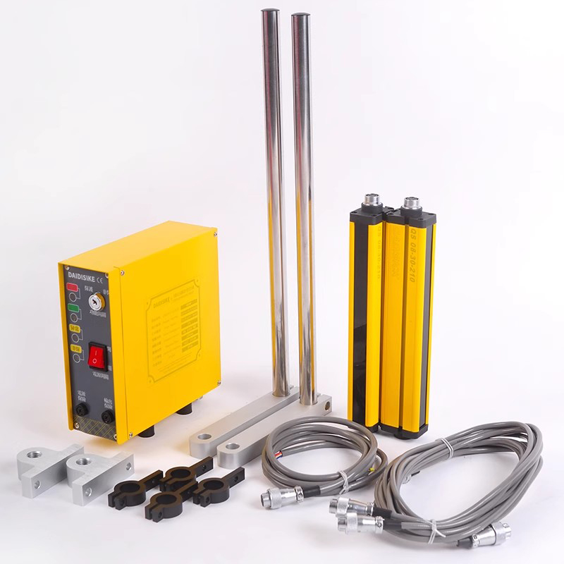
The DQS Press Safety Light Curtain is a candidate to assess after press eligibility is established. Its current catalogue describes matched controller variants and dual relay dry-contact outputs, not a universal OSSD interface. Obtain the exact configuration's manual and current conformity evidence, verify receiving-circuit compatibility, and include its documented response time and reliability data in the complete design. A product recommendation does not simplify away the machine-level validation.
Typical retrofit schemes (topologies)
Scheme A: Mechanical press (part-revolution clutch) + safety light curtain
- Select the required protective-device performance and actual detection capability for the body part and access geometry, not for workpiece thickness alone.
- Connect only the documented safety outputs to compatible safety inputs; dry contacts, OSSDs and safety communication are not interchangeable.
- Use the approved clutch/brake safety circuit and any required final-element monitoring. Define the safe stopped state and prevention of unexpected restart.
- Validate brake monitoring and worst-case stopping performance under the approved test procedure; record the complete time used for positioning.
Scheme B: Engineered replacement or major drive conversion
- Have a competent machine designer determine feasibility and applicable conformity obligations. Changing the drive can change the machine's hazards and control requirements.
- Validate stopping and holding for inertia, gravity and stored fluid energy. Venting pressure can itself cause movement; STO removes drive torque but is not a brake or electrical isolation.
- Select any controlled stop, safe torque removal, valve and mechanical braking functions from their exact approved documentation and verify the complete required safety performance.
- Repeat access, stopping-time, restart and fault validation before considering an optical safeguard or releasing the modified machine.
Schneider Electric's STO documentation distinguishes torque removal from controlled stopping and warns that external forces can require additional braking. That principle does not establish compatibility with any particular press.
Mounting distance & selection notes
- Device and environment: meet the assessed safety performance and verify vibration, oil, contamination, temperature and enclosure requirements separately. Type 4 does not itself imply oil resistance or an IP rating.
- Safety distance: use ISO 13855:2024for the actual arrangement. The introductory S = K × T + C relationship requires the applicable approach and additional distances; include the full worst-case detection-to-hazard-stop chain and document measurement boundaries.
- Control circuit: validate the exact input interface, safety logic, final elements, required monitoring and restart interlock. An ordinary PLC signal is not the protective stop.
- Associated guarding: prevent reaching around, over or under the field and address a person remaining behind it. Only manufacturer-approved deflection mirrors in a validated optical layout can extend a field; a mirror or reflector is not a physical guard.
Project checklist
- Confirm the press is eligible for optical safeguarding, with demonstrated safe stopping and holding for the actual drive and operating modes.
- Measure and record stopping time T (repeat periodically).
- Select suitable Type/resolution/height and IP rating.
- Calculate S distance per ISO 13855 and verify reachability on site.
- Complete PL calculation and validation (ISO 13849-1); retain technical documentation.
- Establish inspection & proof-test routines from the machine and device manuals and applicable rules. Use the specified test piece across the full field with hazardous motion prevented; conduct stop-time and fault tests only under an approved controlled procedure.
FAQ
Can a mechanical press use a safety light curtain?
A part-revolution clutch and brake make a mechanical press a candidate, not automatically suitable as-is. Validate the complete safety control, braking performance, access protection and applicable press requirements. OSHA 1910.217 prohibits presence-sensing point-of-operation devices on full-revolution-clutch presses within its scope; adding a light curtain cannot make that clutch stop mid-stroke.
Do I have to use pneumatic actuation?
No. Actuation type alone does not prove a safe stop. Mechanical, pneumatic, hydraulic and servo machines each need an assessed and validated stopping and holding arrangement, including stored energy and gravity hazards. A major conversion requires competent machine engineering and applicable conformity review; it is not a sensor-only retrofit.
How is the mounting distance determined?
Use the applicable ISO 13855:2024 method for the actual approach geometry and detection capability. S = K × T + C is only an introductory relationship. T must cover the complete worst-case detection-to-hazard-stop chain without omissions or double-counting. Also assess reaching over, under or around the field, presence behind it and reflections.
Keep conclusions separate from illustrative stories: the press retrofit planning narrative explains the evidence a retrofit record needs, but is not a substitute for your machine's measured stopping and validation results.