Frequently Asked Questions
Why would I want Ethernet and discrete outputs from the same LiDAR?
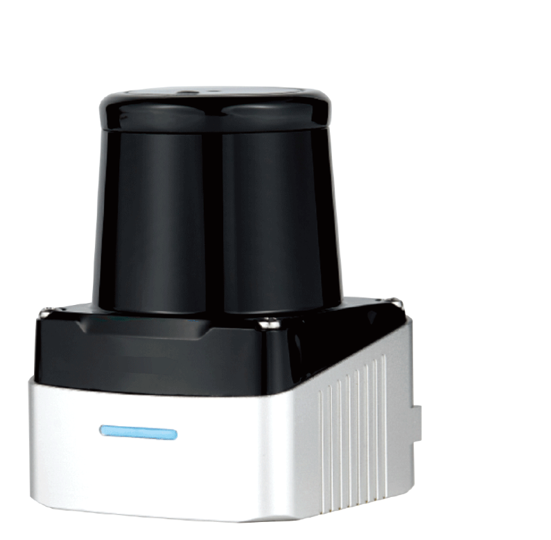
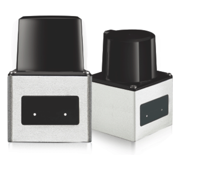
Because most retrofit and mobile-machine projects have two consumers: software that wants the full scan (navigation, monitoring, logging) and a control panel that wants a plain switching signal it can wire today. The DLD50T8N/P serves both simultaneously — 100BASE-TX Ethernet for the data path, hardwired NPN or PNP for the interlock path — so you mount, wire and maintain one sensor instead of two.
N or P — how do I choose the right suffix for my panel?
Match the sensor output to the actual PLC input circuit, not just a label on the input card. DLD50T8N has an NPN sinking output and DLD50T8P has a PNP sourcing output; confirm the compatible input, common terminal and wiring with the controller documentation. The published variant table lists the N model at 50 Hz with 0.08°/0.16°/0.32° resolution and the P model at 100 Hz with 0.32° resolution. Confirm the ordered suffix and configuration before wiring.
Is the discrete output fast enough to bypass network latency for a stop signal?
The discrete output provides a separate hardwired input to ordinary control or warning logic, but scan frequency alone does not establish total response time. Confirm sensor response, output behaviour and PLC processing for the ordered model, then test the complete chain. It is not an OSSD or a certified personnel-protection output; a hardwired connection does not make it one.
Can this scanner satisfy my machine-safety risk assessment?
No. This is a perception/measurement LiDAR, not an IEC 61496 certified safety component; do not use it as the sole means of personnel protection. The discrete output is not an OSSD and no Type, SIL or PL rating is published. When the risk assessment demands a protective device, that is our ST27 Type 3 safety laser scanner — and the two roles should not be blurred in the design review.
What range figure should the zone logic be designed on?
The dual rating is 50 m at 90% remission and 20 m at 10% remission, with ±30 mm accuracy. Tyres, rubber skirts, dark housings and dark clothing behave like the 10% case, so trip distances and slow-down bands for dark targets belong inside the 20 m envelope. The 50 m figure is real, but only for bright, cooperative surfaces.
What is not in the published spec that I should ask about?
The channel count and drive current of the discrete I/O, the Ethernet application protocol above the 100BASE-TX layer, the operating temperature range, connector pinout and power draw are not in the factory sheet we hold. We flag them rather than invent them — send your integration details and we will confirm each point in writing before you order.
Is the downloadable DLD-50D manual a dedicated T8N/P wiring manual?
No. The supplied reference manual lists DLD-50DH, DLD-50DC and DLD-50DP, not DLD50T8N or DLD50T8P. It is provided for background on the DLD-50D platform. Do not transfer its connector pinout, communications settings or parameter values to a T8 unit without written model-specific confirmation. Request the T8 drawing and protocol for your ordered suffix before commissioning.
What are the MOQ, lead time and OEM terms?
MOQ 1 unit; a bench evaluation against your actual PLC input card is the fastest way to settle the N/P choice. Typical lead time is 3–15 days by variant and quantity, confirmed on the quotation. Factory-direct export from China; OEM/ODM cooperation on cabling, labelling and preset zone parameters is available for volume programs through the inquiry form.