
Overhead Crane LiDAR Personnel Detection — Vehicle-Lane Safety Case Study from the Electric Power Industry
DAIDISIKE application case · Published 2026-05-18 · Content updated: 2026-09-05
This electric-power-industry application considers LiDAR monitoring beneath an overhead crane. Tilt, occlusion and load movement determine what a 2D scan can detect; a scan plane does not cover the whole floor volume. DLD30T-5N is a non-safety perception device. Adding a safety relay does not turn its signal into a certified personnel-protection function. The following geometry and workflow require project-specific validation.
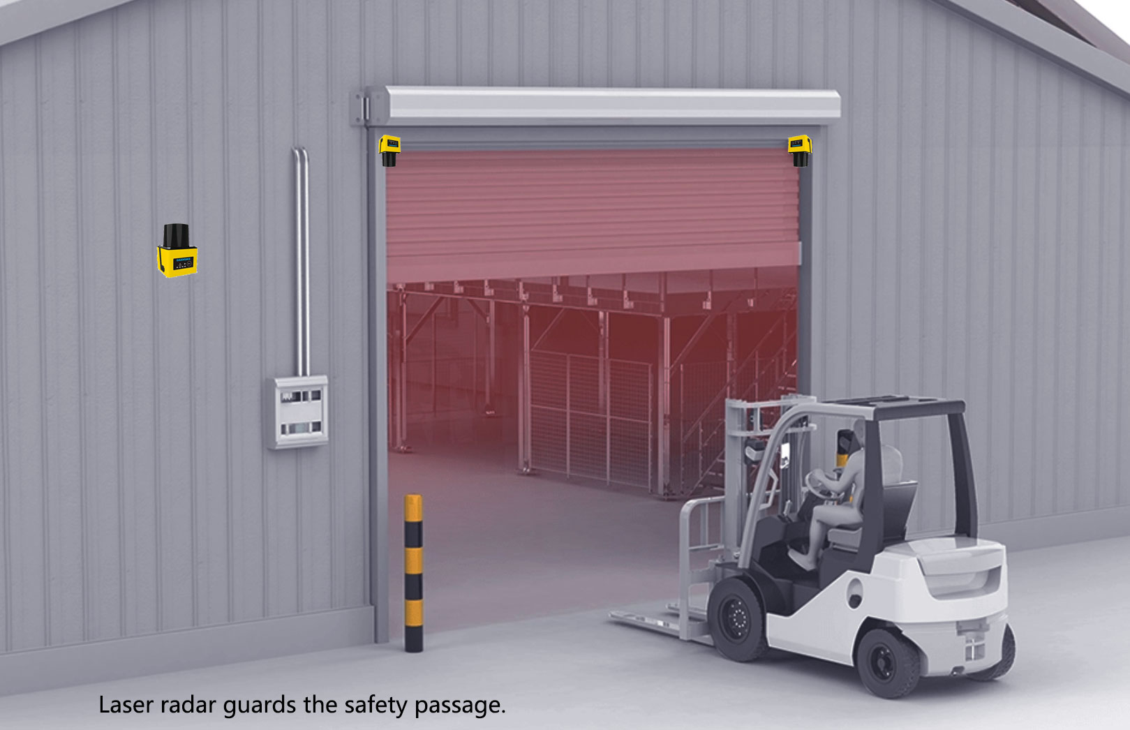
1. The Problem — Bridge Crane Operations Over an Active Vehicle Lane
The original case brief describes an electric-power maintenance hall where an overhead bridge crane shares space with vehicle and pedestrian traffic. Detailed customer records, rated crane capacity and commissioning results are not available with this article. Treat numerical geometry below as a worked example, not proof of a completed safety installation.
The three risks that drove this project:
- Personnel entering the lane while the crane is in motion with a suspended load — falling load risk plus the crane's travel can clip head clearance.
- Forklifts and service vehicles crossing the lane just as the crane arrives overhead — vertical and horizontal motion conflict, with the load being the highest-consequence intersecting object.
- Visual blind spots from the crane cabin — the crane operator sits 6+ m above the floor and the load itself often blocks the line of sight to the area immediately below the hook.
Three traditional safety measures were considered and rejected:
| Measure | Why It Fails Here |
|---|---|
| Safety light curtains | Fixed emitter/receiver pairs work for doorways, not for the entire footprint under a moving bridge crane. The protected area needs to move with the crane. |
| Physical fencing | Blocks the vehicle lane entirely. The whole reason the lane exists is for vehicles to use it. |
| Visual operator monitoring + audible alarms | Relies entirely on human attention. The crane operator's field of view is obstructed by the load. Audible alarms train people to tune them out. |
What was needed: a detection footprint that travels with the crane, doesn't physically obstruct the lane, and produces a deterministic stop signal regardless of operator attention.
2. The Solution — Tilt-Mounted 2D LiDAR With Two-Zone Interlock
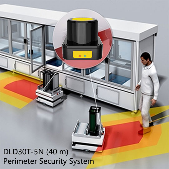
The proposed monitoring layout combines three principles; each requires site verification:
- LiDAR mounted on the crane itself — so the detection footprint travels with the crane; coverage of the actual hazard must still be verified at every relevant load, hoist and travel position. Movement of the sensor does not guarantee uninterrupted detection.
- Tilted scan plane (~20° downward) — the LiDAR is angled so its scan plane intersects a flat floor along a line, not a filled fan-shaped protective floor area. Evaluate where the plane intersects the objects that must be detected. Hook, chain and load positions can enter or shadow the plane and must be checked throughout travel and hoist movement.
- Two-zone polygon fields with graded response — an outer warning zone triggers slow-down (giving people time to clear), and an inner protective zone triggers immediate stop (the hard floor). This matches the general warning/stop concept. Ordinary LiDAR detection zones do not inherit the safety rating of a certified protective field.
The hardware chosen was the DAIDISIKE DLD30T-5N — a non-safety perception LiDAR. The current factory table lists 30 m at 90% remission and 10 m at 10% remission, with Ethernet point-cloud output. The older 40 m label and dry-contact/RS-485 descriptions must not be used as a wiring specification. Consult the LiDAR family by sensing and safety function and the exact model documents before selection.
3. Scan-Zone Geometry — Calculating the Tilt Angle
The center ray of a 2D scanner mounted at height H and tilted down by θ intersects a level floor at horizontal distance R = H / tan(θ). Slant distance to that point is H / sin(θ). These describe one ray, not a ring or a filled protected floor area.
Center-ray slant distance: L = H / sin(θ)
A tilted 2D scan plane intersects a flat floor along a line; actual targets intersect the scan plane at their own heights.
For the center ray, the horizontal distance formula is:
Illustrative geometry only: H = 6 m and θ = 20°. These are not verified customer measurements:
The center ray reaches the floor about 16.5 m horizontally away and about 17.5 m along the beam. Other azimuths have different intersections; a 270° scan does not fill the floor area beneath the crane. Compare slant range with the target-reflectivity limit and assess people, loads and occlusions throughout the full motion envelope.
| Crane Height H | Tilt θ = 15° | Tilt θ = 20° | Tilt θ = 25° | Tilt θ = 30° |
|---|---|---|---|---|
| 4 m | 14.9 m | 11.0 m | 8.6 m | 6.9 m |
| 6 m | 22.4 m | 16.5 m | 12.9 m | 10.4 m |
| 8 m | 29.9 m | 22.0 m | 17.2 m | 13.9 m |
| 10 m | 37.3 m | 27.5 m | 21.4 m | 17.3 m |
| 12 m | 44.8 m | 33.0 m | 25.7 m | 20.8 m |
The table gives center-ray horizontal distances only. It does not determine lane coverage or a safety margin. Use a three-dimensional layout and controlled detection tests at relevant target heights; verify shadowing by the load and crane structure.
4. Installation Walkthrough — 8 Steps from Survey to Acceptance Test
The eight steps below are an engineering review workflow. No installation duration, cost or successful acceptance result is established by the source material available here.
Step 1: Survey the vehicle lane
Measure the lane, load and crane motion envelopes. Identify pedestrian access, suspended-load hazards and the safety functions required by the risk assessment.
Step 2: Calculate the tilt angle and scan-zone geometry
Calculate center-ray horizontal and slant distances, then evaluate the complete scan-plane intersection and occlusions. A tilted 2D scanner does not create a filled protected floor area.
Step 3: Mount the LiDAR on the crane main beam
Use a rigid, documented mounting design approved for the crane. Verify vibration, clearances and repeatable alignment throughout travel.
Step 4: Run power and signal cables along the crane
Route power and the actual supported interface according to the exact model and crane manuals. Confirm strain relief, shielding and moving-cable suitability; no generic pinout is provided.
Step 5: Configure monitoring zones and identify any separate safety-field requirement
Configure non-safety monitoring and warning zones for DLD sensing. Where a personnel-protective field is required, specify an appropriate safety-rated device and validate all operating states.
Step 6: Validate the actual interface and crane control architecture
Have the crane safety designer establish compatible sensing, logic and final elements. A relay does not certify non-safety LiDAR; do not infer a dry-contact stop interface from legacy descriptions.
Step 7: Validate at maximum crane speed
Validate detection and complete stopping performance in a controlled test area using suitable test objects, never a person exposed to moving equipment. Check faults and worst-case permitted motion against the approved design.
Step 8: Operator training and signage
Train operators in permitted operation, fault response, inspection and restart. Record configuration and acceptance evidence before release.
5. Interlock Wiring — Tying LiDAR Outputs Into the Crane Control Loop
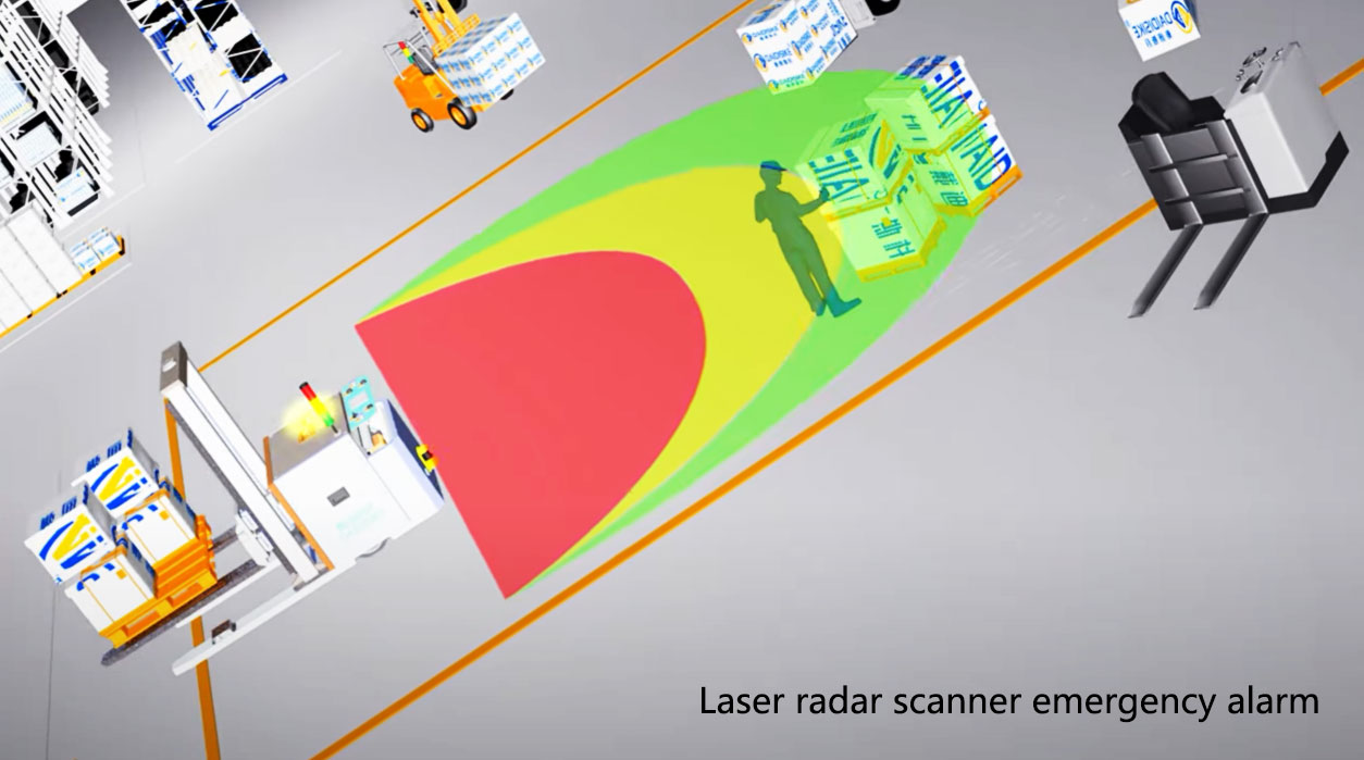
The table describes intended functions, not DLD30T-5N pin assignments. Confirm the exact output hardware and use a suitably rated independent detection/control chain wherever personnel safety is required.
| LiDAR Output | Triggered By | Crane Action | Wired To |
|---|---|---|---|
| Warning request (concept) | Object in a configured monitoring zone | Operational slowdown request and alarm | PLC input + audible alarm relay |
| Safety stop demand (separate validated function) | Detection by a suitable protective device | Defined safe state based on crane risk assessment | Compatible safety logic and final elements, validated together |
A safety relay such as DAIDISIKE DA31 cannot add missing safety integrity to a non-safety LiDAR. Establish the required safety performance for sensing, logic, braking and final elements together; verify compatibility from the manuals. Preserve existing crane safety functions and address suspended-load hazards separately.
For event logging, first confirm the actual interface and available data fields. Do not assume built-in timestamps, zone IDs or Modbus registers. Diagnostic data may support maintenance but does not prove a safe stop.
6. Hardware Recommendation
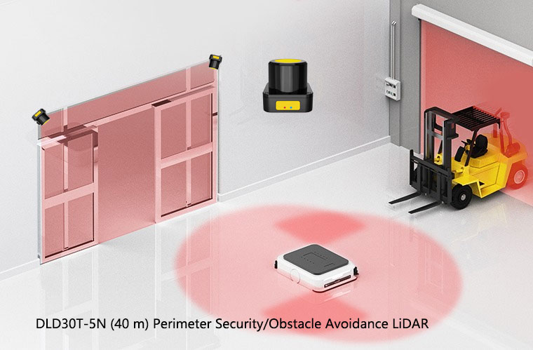
DAIDISIKE DLD30T-5N — non-safety perception
- Detection range: factory table: 30 m at 90% remission; 10 m at 10% remission.
- Scan rate: 10–30 Hz; scan frequency is not a certified safety response time.
- Laser: 905 nm Class 1; this does not establish functional safety.
- Enclosure: IP67; assess actual contamination and cleaning exposure.
- Interface: current factory table lists Ethernet point-cloud output; confirm the delivered variant.
- Body: current table: 50 × 50 × 76 mm, 148 g; check installation drawings.
- Operating temperature: −10 °C to +55 °C; storage limits are different.
Shorter-range alternatives for lower cranes: the DLD05A3-3N / DLD20A5-5N (5 m / 20 m) for jib cranes and small bridge cranes; the 5JPTG / 10JPTG (5 m / 10 m) for ultra-compact installations.
7. Where This Same Pattern Applies — Beyond Electric Power
The customer in this case study is in the electric power industry, but the underlying safety pattern — moving overhead equipment + shared ground-level traffic area — appears in many other industries where the same LiDAR + tilt-mount + interlock concept requires a fresh risk assessment and design:
Steel Mills
Bridge cranes moving ladles of molten steel above the rolling mill floor. Slag splash and high ambient temperature make IP67 + extended temperature range critical.
Automotive Stamping
Plant overhead cranes moving die sets between presses while forklifts cycle steel coils underneath. Tilt-mounted LiDAR keeps die-change traffic safe without halting press operations.
Container Ports
Quay cranes and rubber-tired gantry cranes above truck lanes. Higher mounting requires checking slant distance, target remission, scan geometry and independently validated personnel protection.
Aerospace Manufacturing
Overhead cranes moving fuselage sections and wing assemblies. Assess lifting hazards and applicable machine-safety requirements; ordinary LiDAR plus a relay does not establish an approved protective architecture.
Wind Turbine Component Assembly
Cranes moving multi-ton blade and nacelle components. Long bays mean long crane travel paths intersecting multiple staging zones.
Shipyards
Goliath gantry cranes moving ship-block sections. Outdoor environment + corrosion + tidal vibration — IP67 + 905 nm Class 1 laser are well-suited.
8. Results Evidence Required Before Reusing the Design
- Incident evidence: obtain dated incident and near-miss records with a defined observation period.
- Availability evidence: classify warning events, stops and false detections against logged operating cycles and conditions.
- Safety evidence: retain verified detection coverage, stopping tests and fault response; absence of incidents alone does not validate safeguarding.
- Commercial evidence: confirm installation cost, labor and rollout scope from project records before quoting them.
- Current limitation: the previous numerical outcome, payback and rollout claims cannot be substantiated from the material provided with this article; they are not presented as measured results.
9. Frequently Asked Questions
Why use LiDAR for crane personnel detection instead of safety light curtains or fencing?
LiDAR may monitor changing geometry without a physical beam receiver, but a 2D scan does not see an entire three-dimensional space. Fencing, controlled access, exclusion zones and other protective devices may still be required. Choose safeguarding from the crane and suspended-load risk assessment.
What detection range and resolution do I need for an overhead crane application?
Calculate slant distance to the required targets and check detection capability at their worst-case reflectivity. DLD30T-5N is listed at 30 m on 90% remission and 10 m on 10% remission; these are sensing ranges, not certified protective ranges. Height, occlusion and every load position require verification.
How do I integrate the LiDAR outputs with the existing crane control system?
Obtain the exact model wiring and interface documents. Do not assume dry-contact outputs from a legacy description: the current DLD30T-5N factory table lists Ethernet point-cloud data. A personnel-safety stop needs a suitable protective device, compatible safety logic and validated final elements.
What about false alarms from the crane's own moving parts — chains, hook block, hoisted load?
Check the entire crane and load motion envelope. Excluding a hook or load from detection may also hide a person. A fixed tilt angle cannot guarantee that chains and loads stay outside the scan plane. Supplement detection or restrict access where coverage cannot be proved.
Does this configuration meet ISO 13849 / IEC 61496 safety standards?
No safety performance level follows from combining DLD30T-5N with DA31. DLD30T-5N is non-safety perception LiDAR; a relay does not convert it into a Type 3 protective device or establish PL c, PL d or SIL 2. The complete sensing, control and stopping function must meet the assessed requirements.
What happens during a power loss or LiDAR fault?
Verify fault and power-loss behavior from the exact hardware and safety architecture. Ordinary network or switching outputs must not be assumed to have safety OSSD diagnostics. Test loss of power, communication and relevant faults under a controlled procedure and confirm the specified safe state.
Can this same approach work for other crane applications — gantry cranes, jib cranes, port quay cranes?
The geometry concept may be considered for other cranes, but each needs a separate assessment of structure, loads, occlusion, travel, environment and safeguarding. Nominal range or a similar mounting location does not establish that the original design can be reused safely.
10. Related Reading
DAIDISIKE LiDAR Scanner Category Overview
Model categories, detection limits and safety-versus-sensing selection.
DLD30T-5N Product Page
Specs, dimensions, technical drawings, and ordering details for the LiDAR used in this case study.
Safety Scanner vs Industrial LiDAR
When to pick a safety-rated scanner vs an obstacle-avoidance LiDAR for mobile and overhead applications.
Anti-Collision Laser Scanner Setup Guide
Step-by-step configuration of warning + protective zones for factory floor applications.
DA31 Safety Relay Module
Safety-relay documentation; compatibility and complete-function performance require verification.
More Solution Case Studies
Customer applications across safety light curtains, LiDAR, infrared detectors, and door locks.
Have a Similar Crane Safety Application?
Provide crane height, lane geometry, load envelope, permitted motion, required safety function and environmental conditions. These let engineering assess whether the proposed sensing geometry is suitable and what documentation and validation are needed. No response time or reference drawing availability is promised here.
Contact DAIDISIKE Engineering →