
Content updated: 2026-09-05. Application overview, not a verified customer installation.
The EV battery manufacturing safety overview covers the plant-level context; this page follows pouch-cell operations in more detail. Cell format does not uniquely determine manufacturing method: prismatic cells may also be stacked, and equipment configurations differ. Use the actual machine sequence, manual tasks and maintenance access rather than a format stereotype.
The light-curtain selection range helps shortlist device families after those risks are defined. Each station below identifies design questions, not a complete specification or proof that a named DAIDISIKE model is suitable.
Why pouch is its own guarding problem
Three process considerations affect the pouch-cell scenario below; they are not exclusive to every pouch format or absent from other formats.
Stacking changes the moving-axis and reload hazards. In a Z-fold process, electrode sheets are placed into a folded separator. Other stacking or winding routes are possible. The relevant risks include grippers, magazine interfaces, separator handling and trapped energy; no universal layer count, production rate or placement accuracy is assumed here.
Filling, degassing and sealing have more than motion hazards. Vacuum, pressure differences, hot tooling, electrolyte and possible residual energy need coordinated controls. Door locking and release conditions must follow the actual chamber and process design; a light curtain does not contain liquids, gas or a pressure event.
Cell integrity and safe stopping must be considered together. Damage can create electrical, chemical and thermal hazards. Define safe gripper/load behavior on a protective stop without compromising personnel protection. A product-quality concern never justifies muting an unresolved safety fault.
Walking the line, station by station
1. Notching and die-cutting
Coated electrode coils arrive at the notcher, which cuts the anode and cathode tab geometry from the coated foil. Possible processes include mechanical die-cutting and laser notching. Each machine has its own tooling, emissions and enclosure requirements. They are different safety problems.
A mechanical notcher can have press-stroke and in-running nip hazards. Fixed or interlocked guards are candidates; an access curtain is appropriate only where the full hazard can reach its safe state before access and all other routes are addressed. Select declared detection capability from the actual approach, not a blanket 14–20 mm value. A laser process additionally needs suitable beam containment and interlocked emission control. Stopping axes or detecting a hand does not by itself stop hazardous optical exposure.
2. Z-fold stacking
This is the heart of a pouch line. A Z-fold stacker pulls a continuous separator web back and forth in a zig-zag while robotic vacuum grippers insert pre-notched anode and cathode sheets from the two sides. The build platform indexes down as layers accumulate. Vision systems verify alignment between every placement.
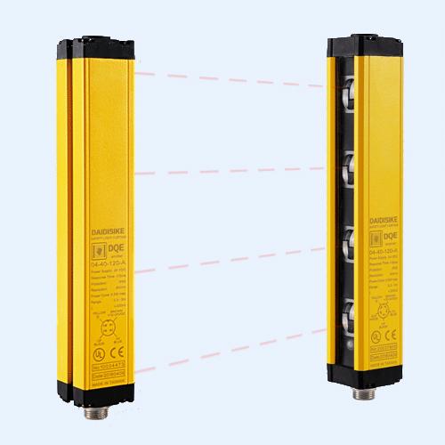
Assess gripper travel, separator tension and the magazine interface, including access during reload and after a stop. A transfer drawer or interlocked enclosure may separate loading from hazardous movement. If a curtain or rated scanner is used, validate detection geometry, stopping performance, remaining presence and restart prevention. The DQC product data does not establish a Type 4 rating, finger detection or dry-room approval for this application; no installed use is claimed here.
3. Tab welding
Once the stack is complete, the protruding anode and cathode current collectors are trimmed and welded to the cell tabs. Ultrasonic welding is one joining method for thin foils; the actual method and stack construction determine process hazards. The hazards are the ultrasonic horn, which is a serious crush and pinch source, and the trim knife, which is sharp by definition. Guarding is a hard enclosure with suitably interlocked access. A point-of-operation curtain is only a candidate if stopping and access can be validated; it does not contain noise, ejected material or emissions. Ultrasonic tooling can also generate enough audible noise that hearing protection is part of the local PPE plan — that is not a light-curtain question, but it belongs in the same risk assessment.
4. Pouch packaging, electrolyte filling and pre-seal
The stack is dropped into a pre-formed aluminium-laminate pouch, three sides are heat-sealed, and the cell goes into a vacuum chamber for electrolyte filling. The fill is done under vacuum to draw electrolyte uniformly into the stack porosity. After fill, a pre-seal closes the cell with an electrolyte reservoir still attached.
Determine the chamber's safe access conditions, including pressure, process isolation and remaining chemical or thermal hazards. Use suitable guard locking where the hazard persists after a stop command; do not assume that any DX-series lock monitors process-safe pressure. A curtain may address adjacent loading motion but cannot substitute for containment or verified safe chamber release.
5. Formation, aging and degassing — the scope warning
Pre-sealed cells go to a formation rack for their first charge. This is where the solid electrolyte interphase forms on the anode, and cell faults can present venting or thermal hazards. After formation, cells are opened in a second vacuum chamber to release formation gas, then final-sealed.
Motion protection is not thermal-runaway protection. The overall risk assessment must cover both, with qualified electrical, chemical, fire and machine-safety input. Detection, ventilation, containment and suppression require a hazard-specific design; this guide does not prescribe a suppression agent or a universal gas-detection list. Related systems may exchange validated commands, but one does not replace the other.
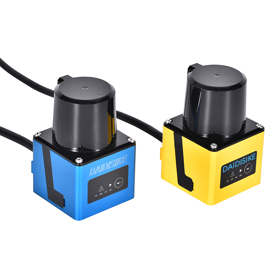
For shuttles and gantries, choose physical guards, interlocks, curtains or rated safety scanners from actual access geometry, occlusion and stopping performance. The SDLD-05A non-safety area sensor and DLD families must not provide the required protective stop. A warning or ordinary slowdown from these sensors is supplementary. Where a rated scanner is required, review the ST27 Type 3 / PL d / SIL 2 scanner as a documented-capability candidate, subject to exact application, environmental, coverage and control validation.
6. Aging, grading and capacity sort
Cells sit on aging shelves for days, then run through a capacity grading station that cycles them and bins them by performance. Handling speed and severity vary by machine; the relevant assessment still distinguishes between machine safety (handling) and process safety (any cell venting late in life). Assess handling access, remaining energy and electrical/process hazards together; a guarding method from another rack is not automatically suitable.
7. Module assembly — cell stacking, busbar welding, BMS install
Graded cells are stacked into modules, compressed in a fixture, and the cell tabs are joined to module busbars by laser welding. A typical module cell contains a robot for cell placement, a press for compression, a laser welder, and a BMS install station. The enclosure must address robot, compression, laser and manual intervention hazards together.
A suitable enclosure and controlled access are typical starting points. Select the access device from required detection and stopping behavior, not a blanket 30–40 mm value. Material pass-throughs need a supported, validated muting or other safeguarding design that prevents access beside, behind, underneath or on the load. Four sensors alone do not prove this. The pallet-exit muting scenario sets out the sequence and recovery questions without claiming a verified installation.
Alongside mandatory laser containment, assess possible optical and electromagnetic interference from the welding equipment. Plume from the weld and stray reflections can interact with a poorly-immunised curtain, and the laser power supply throws fast switching noise that couples onto the safety I/O. Specify a curtain with strong interference rejection, apply the exact manuals' cabling and bonding requirements, and verify the protective device under actual welding conditions. Do not add ferrites, alter response filters or change alignment without checking manufacturer permission and revalidation. We have a deeper discussion of optical interference on our light curtain vs scanner page, which is the right next read if you are scoping the perimeter of a multi-robot module cell.
8. Pack assembly and end-of-line testing
Modules are joined into a pack frame, the cooling plate and BMS are installed, the pack is sealed, and it goes to end-of-line test. EOL includes hi-pot insulation resistance, sometimes a functional charge/discharge, and final marking.
Pack handling introduces heavy-load, lifting and access risks; robot speed alone does not determine stopping performance. Measure the relevant full chain under the required load and operating modes. High-voltage testing adds electrical isolation, discharge and verified safe-access requirements, including the battery's own stored energy. A stopped probe or open test-enable signal is not proof of absence of hazardous voltage. Use a suitably interlocked and, where needed, locked test enclosure; a light curtain cannot contain an electrical event or replace safe-voltage verification.
Station-by-station guarding summary
| Station | Primary mechanical hazard | Recommended safeguard |
|---|---|---|
| Notching / die-cutting | Tool stroke, web nip; laser emission where applicable | Suitable enclosure/interlocks; any access ESPE requires stoppability and detection assessment |
| Z-fold stacking | Gripper axes, separator tension, magazine reload | Separate loading from motion; validate any curtain/scanner and remaining-presence prevention |
| Ultrasonic tab welding | Horn/fixture crush, trim knife, noise | Suitable enclosure and interlocks; assess manual loading and emissions separately |
| Pouch forming + electrolyte fill | Hot jaws, chamber pressure difference, chemicals | Containment and verified safe-access/locking; curtain only for suitable adjacent motion |
| Formation & aging racks | Handling axes plus electrical/thermal/process hazards | Coordinated hazard controls; DLD/SDLD not protective-stop devices |
| Degassing & final seal | Pressure, hot jaws, cell contents | Safe chamber release and containment; qualified process review |
| Capacity grading / sort | Handling, test energy, remaining cell energy | Validate mechanical access and electrical safe state; no generic device substitution |
| Module assembly | Robot, compression, welding emissions | Suitable enclosure; supported pass-through control and all person-access paths assessed |
| Pack assembly | Robot, heavy loads, lifting and fastening | Guard actual access and suspended/stored-energy hazards |
| EOL electrical test | Voltage and stored energy plus probes/handling | Interlocked/locked access as required; isolation/discharge verification, not enable-only |
| Palletising | Robot, heavy load, material exit | Validated detection/stopping and material transit; no ordinary sensor safety stop |
This is a starting point for the conversation, not a specification. Every station still needs its own risk assessment, the applicable positioning assessment and its own verification of the achieved Performance Level across the full safety function. The table tells you which family of device to reach for. It cannot tell you exactly where to mount it on your machine.
The recurring mistakes — pouch-specific edition
Treating the curtain at the formation rack as fire protection. A curtain detects intrusion for a validated protective function; it does not detect or suppress thermal runaway. Define each hazard-control function and its dependencies in one coordinated risk assessment.
Muting that lets an operator shadow a module. Do not assume two sensors fail and four succeed. Validate the supported geometry, timing, fault response and all access paths. Use specified test objects with hazards disabled, then separately controlled functional tests; an arbitrary wooden block is not an acceptance method.
Unverified dry-room or welding-environment claims. Check permitted humidity, condensation, temperature, ESD, particles, cleaning and optical/EMC conditions for the exact assembly. MTTFd is not a service-life or contamination-suitability specification. Investigate false trips without bypassing protection.
Confusing device capability with achieved performance. Assess all required subsystems and validation evidence. A Type 4 component does not automatically produce PL e, and a single contactor cannot be assigned a generic PL c without evaluating the design.
Changes without impact assessment. Speed, payload, tooling, scan mode, control settings or material-routing changes may affect stopping or access. Review those effects and repeat relevant validation before release; throughput alone does not predict stop time.
Where DAIDISIKE fits, honestly
Review the DQC data and DQSA area-device data against the exact required function; neither a family name nor this article establishes safety approval. DLD/SDLD remain non-safety. Guard locks require verified holding, monitoring and safe-release behavior for the actual chamber; no DX blanket suitability is implied.
Submit the station layout, access tasks, environmental limits, required safe states and exact control interfaces through the station-level device review enquiry. A candidate list must state missing evidence and cannot replace the machine builder's validation.
The bottom line
Keep the purpose of each control explicit while coordinating the overall risk assessment. Mechanical, electrical, chemical, optical and thermal hazards can interact; none may be dismissed because another team owns it. Select and validate safeguards for the actual station, not a generic production-rate target or a single purchasing part number.
Sources: RWTH Aachen PEM battery-production process guide; OSHA laser-hazard standards overview; OSHA electrical work practices and stored energy; IEC 62046:2026.