
Wiring the MQ Essence Edition Into a Real Machine — Sync Modes, Outputs, Blind Zones, Commissioning
What the MQ Is, in One Integrator's Paragraph
The MQ "Essence Edition" manual describes a transmitter/receiver pair in a 29 × 30 mm aluminium profile, pitches of 10/20/40 mm, beam counts from 4 to 256, sensing bands from 0.2 m out to 7 m, response inside 10 ms, IP65, with factory-terminated 3 m cables ending in direct M12 aviation connectors. This page is the integrator's view — how it wires, where it hides its blind zones, how it behaves next to a second curtain, and what to test. The manual states TUV/CE but does not provide Type/PL classification or certificate scope here; those remain a selection hold point for a rated safety function. For the full model tables, detection-class photos and ordering, the MQ series page in the DAIDISIKE product catalogue is the companion document.
Optical Sync vs Wire Sync: What Actually Changes at the Terminals
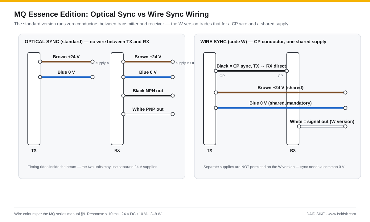
The MQ manual describes standard optical synchronization without a dedicated TX–RX sync conductor: a narrow-angle emitter and a cyclic scanning algorithm embed the timing in the beam itself, so the transmitter wires with exactly two conductors — brown +24 V, blue 0 V — and the receiver adds only its output wires. The practical wins are real: one less cable to route and protect, one less connector to fail, and — the one integrators care about on wide machines — the two units may use separate compliant supplies according to manual §9.2. That does not remove the need for a correct receiver-to-input reference or the machine's required protective bonding and supply design.
The wire-synchronised variant (order code W) exists for specifications that demand an electrical reference: its black CP conductors connect TX to RX directly, and that shared signal imposes a shared supply — one 24 V rail, one 0 V as specified by the manual. The manual describes equivalent detection behaviour, but signal assignments differ: black is CP on W, while white is the ordered signal output. Verify its exact polarity and logic; do not apply the standard optical black=NPN mapping to W.
One Output, Chosen Honestly: NPN or PNP, NO or NC
On the standard optical version, black is NPN and white is PNP. The rule from the manual is strict: connect one, insulate the other, never both. NPN (sinking) suits input circuits with a common positive rail; PNP (sourcing) suits common-negative inputs — the usual convention on European-specification machinery. Logic is ordered, not configured: code C gives NC (conducting while clear), code O gives NO. Check the exact input and loss-of-power behavior; NC alone does not detect every short or internal failure and is not a certified safety architecture.
And the honesty note that belongs in the specification meeting, not the commissioning crisis: this is a single switching output, not a dual OSSD pair, and the manual — while stating TUV/CE certification — prints no IEC 61496 Type class and no ISO 13849 PL. Where the risk assessment calls for a rated protective function, obtain exact-model evidence before selection, or assess a documented alternative from the DQT4 family whose pages state the Type 4 architecture explicitly. Built-in reverse-polarity and output short-circuit protection cover the two classic commissioning accidents, not the architecture question.
Interface decision — not an approved stop circuit
| Version / lead | Documented role | Hold point |
|---|---|---|
| Optical: black or white | Select one NPN or PNP output | Insulate unused lead; verify receiving input |
| W: black / white | CP sync / ordered signal output | Confirm variant output logic before wiring |
| Personnel-protection function | Not established by one NC output | Exact Type/PL and controller compatibility required |
No DA31 compatibility or fault-detection coverage is established by this table. An ordinary PLC input may monitor process status but is not a protective-stop evaluator; do not promote a single MQ output to a rated safety function by adding a relay.
Decoding the Ordering Code Before It Decodes You
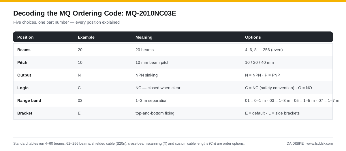
Every MQ option discussed on this page lives in one part number. Take MQ-2010NC03E: twenty beams, 10 mm pitch, NPN output, NC logic, range band 03 (1–3 m), top-and-bottom brackets. Two of those positions do real integration work. The range band (01/03/05/07) is not a maximum to brag about but a tuning choice — order the band your actual separation falls in, because an undersized band starves the signal margin and an oversized one worsens crosstalk between neighbouring curtains. And the logic code is where NC gets locked in, per the section above.
Blind Zones and the 57 mm Nobody Budgets For
Two formulas size every MQ. Protection height: H = (beams − 1) × pitch, measured beam-centre to beam-centre. Housing length: L = beams × pitch + 57 mm — the constant being the 12 mm top cap plus the 45 mm bottom cap that houses the cable outlet. Between those two numbers hide the blind zones: half a pitch beyond the first and last beam, at each end, where the housing exists but no detection does. Twenty-four beams at 20 mm pitch protect 460 mm of opening inside 537 mm of aluminium — and the mounting has to put those half-pitch margins over solid guarding, plus bending clearance for the cable below the bottom cap. Machine layouts that skip this arithmetic discover it as a reachable gap at audit time.
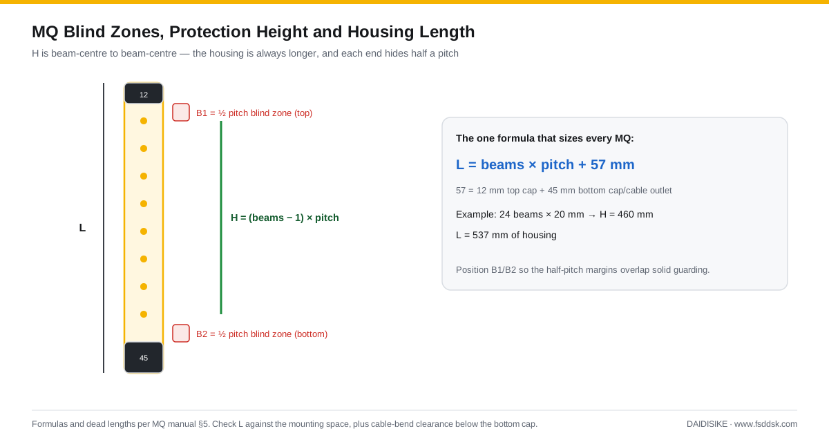
Drawing check: manual §6.1 lists MQ0410 length L as 117 mm, while the general formula gives 4 × 10 + 57 = 97 mm. This guide does not resolve that discrepancy: obtain the approved MQ0410 dimension drawing before drilling or fixing an installation. The 24-beam/20 mm example above agrees at H = 460 mm and L = 537 mm.
Two MQ Curtains Side by Side Without Crosstalk
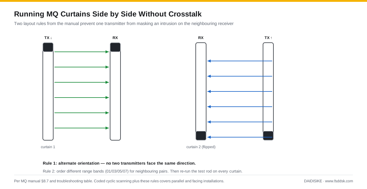
Coded cyclic scanning gives the MQ strong immunity, but physics still allows one transmitter to illuminate the neighbouring receiver when two curtains share a space. The manual's two layout rules close that door: alternate the orientation of adjacent pairs (transmitter up on the first, down on the second) so no two transmitters face the same direction, and consider different permitted range settings only where each still covers its installed span. Do not invert one unit within a matched pair. After any such layout, the test rod goes through every curtain again — interference is proven absent, not assumed.
Commissioning the MQ: Short Version of a Non-Negotiable
- Confirm TX and RX are the same model code and a factory-matched pair, both cable outlets pointing the same way — inverted mounting reverses the scan sequence and the pair will never synchronise.
- Power up, let the CPU self-check finish, and require a stable, flicker-free clear indication during the controlled check. Flicker can indicate alignment, contamination, interference or an electrical fault; diagnose it using the exact manual before acceptance.
- Pass the matching rod — Φ15 / Φ25 / Φ45 mm for 10/20/40 mm pitch — with hazardous functions disabled, top to bottom at the prescribed three positions and accessible boundaries; blocked indication must be continuous, gapless, at every point.
- Qualified personnel must validate the required stop and restart functions under controlled conditions, without entering the hazard. Fault simulation requires an approved safe procedure; do not unplug energized connectors. The manual's before-shift checks do not replace the missing Type/PL evidence or approve the application.
Before considering a rated protective installation, resolve the safety-evidence hold point. Positioning then requires the complete detection-to-safe-state time, documented detection capability and applicable ISO 13855 approach case, not just the ≤10 ms sensor value and a handheld stopwatch. The installation and wiring engineering index separates these integration decisions from catalogue ordering.
Source: MQ Series Essence Edition manual, §§5–6 (dimensions), §9 (wiring), §10 (test procedure) and §13 (limits). The current article corrects inference beyond that document; it does not certify the MQ or replace the applicable machine assessment.
Frequently Asked Questions
How is the MQ light curtain wired without a synchronisation cable?
The standard optical version uses timing carried by the light path, with no dedicated TX–RX sync conductor. The manual lists brown +24 V and blue 0 V, with black NPN or white PNP on the optical receiver; use only the selected output. Separate supplies are permitted by the manual, but the receiving input still needs the correct electrical reference.
When would I order the wire-synchronised (W) version instead?
Use option W only for a specified compatible design. Its black CP leads link TX and RX with a shared supply and 0 V; white is the ordered signal output. Do not copy the optical version's black=NPN connection onto W. Confirm the exact variant pinout and output polarity before wiring.
Does the MQ have dual OSSD outputs like a Type 4 curtain?
The manual describes one selected switching output, not a dual OSSD pair. It states TUV/CE but does not publish an IEC 61496 Type or ISO 13849 PL here. Adding a safety relay does not create that rating. Hold a proposed personnel-protection application until exact model and system evidence establishes suitability.
Why should the output be NC rather than NO?
The manual defines code C as conducting while the field is clear and changing state on interruption or supply loss. That can support the intended input logic, but NC does not diagnose every fault and does not establish safety integrity. Check both the documented device behavior and receiving control design; NO/NC labels alone cannot approve a safety circuit.
How big are the MQ's blind zones and how do I place them?
The manual defines half-pitch optical end margins plus 12 mm top and 45 mm bottom caps, with H=(n−1)×pitch and L=n×pitch+57 mm. Keep reachable gaps closed. One table discrepancy remains: MQ0410 lists L=117 mm while the formula gives 97 mm, so obtain its approved drawing rather than choosing either value silently.
What test rod does the MQ need at commissioning?
The manual specifies opaque rods of 15, 25 and 45 mm for 10, 20 and 40 mm pitch respectively. With hazardous functions disabled, follow the complete prescribed sweep near TX, midpoint and RX and check relevant boundaries. Qualified personnel must validate stop, fault and restart behavior separately under controlled conditions; passing a rod test does not establish an unpublished safety rating.