
DX-C1 Coded Magnetic Safety Interlock Switch
Non-contact guard-door monitoring that keeps working when the door itself no longer closes perfectly — sequence-coded magnets, a wide 17 mm sensing range and reed outputs that wire straight into your safety relay.
- Coded actuation — a plain magnet will not trip it
- Sensing distance up to 17 mm, Z and Y directions
- 2NC / 1NC+1NO / 2NO reed contact outputs
- Series connection: many doors, one safety relay input
- IP65 flame-retardant housing; IP67/IP68 on request
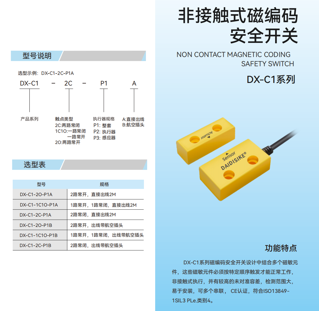
Why a Coded Magnetic Switch for Guard Doors?
Mechanical tongue interlocks assume the guard door still closes exactly where it did on day one. On real production floors, hinged doors sag, sliding tracks wear and fence panels get refitted a few millimetres off. The DX-C1 was designed for exactly this situation: its sensor and coded magnetic actuator only need to arrive within a 17 mm window of each other, in either the Z or Y direction, for the door to be reported closed.
Unlike a household-style reed sensor, the DX-C1 contains multiple magnetically sensitive elements that must fire in a defined sequence. Only the paired coded actuator produces that sequence — taping an ordinary magnet to the frame does not. The result is a non-contact switch with genuine defeat resistance and simple reed contact outputs that wire straight into a safety relay.
Within the DAIDISIKE door-hardware family, the DX-C1 sits between the mechanical DX-D2/DX-D3 tongue switches and the RFID-coded DX-R1: pick it when you want non-contact convenience and magnet-defeat resistance without moving up to an electronic switch.
How Sequence-Coded Actuation Works
Original schematic — simplified for illustration; element count and layout are representative, not a construction drawing.
Technical Specifications
| Actuation principle | Multiple magnetically sensitive elements triggered in a defined sequence by a coded magnetic actuator |
|---|---|
| Sensing distance | Up to 17 mm in the Z and Y directions |
| Output configurations | 2C = 2 NC / 1C1O = 1 NC + 1 NO / 2O = 2 NO (reed contacts) |
| Contact electrical rating | 200 mA max. output current (pilot duty — feed a safety relay, not a load) |
| Response time | 5 ms |
| Operating frequency | 1 Hz |
| Operating distance | Closing (make) min. 8 mm; opening (release) max. 17 mm |
| Connection | A = 2 m pre-wired cable / B = quick-disconnect (aviation-style) plug |
| Series connection | Multiple switches per safety relay input (2NC versions) |
| Protection rating | IP65 standard; IP67 / IP68 available on custom order |
| Ambient conditions | Operating temperature -10 °C to +55 °C; relative humidity 5 % to 95 % |
| Housing material | Flame-retardant, heat-resistant thermoplastic |
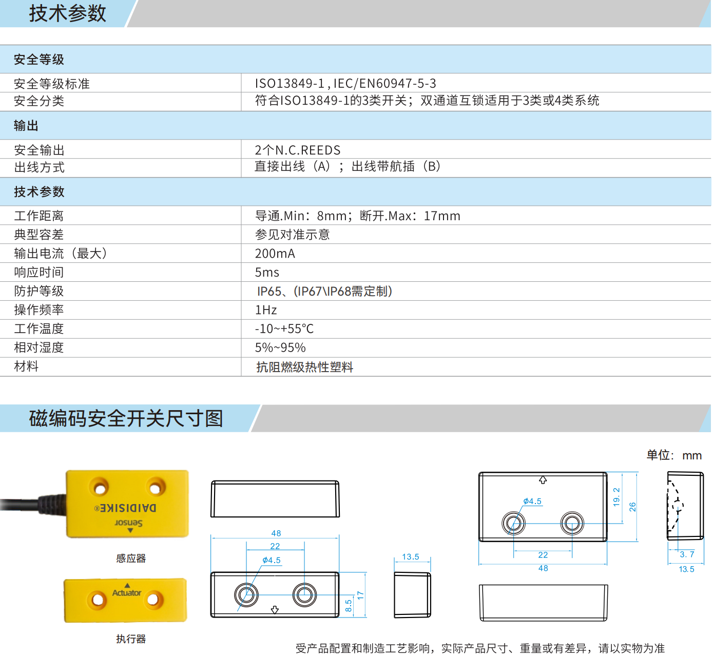
| Dimensions | Sensor and actuator 48 × 26 × 13.5 mm; two Ø4.5 mm mounting holes on 22 mm centres |
| Operating voltage | Contact factory — not stated in the factory specification sheet |
| Safety design basis | CE marked (per valid certificate and applicable models). Catalogue rating: ISO 13849-1 SIL 3 / PL e / Cat. 4 — a functional-safety circuit-design reference; the level actually achieved depends on the complete circuit including the safety relay and wiring. |
Model Selection (6 Variants)
| Model | Contacts | Connection | Typical use |
|---|---|---|---|
| DX-C1-2C-P1A | 2 NC | 2 m cable | Dual-channel safety loop, fixed installation |
| DX-C1-2C-P1B | 2 NC | Quick-disconnect | Dual-channel safety loop, fast swap |
| DX-C1-1C1O-P1A | 1 NC + 1 NO | 2 m cable | Safety channel + PLC door-status feedback |
| DX-C1-1C1O-P1B | 1 NC + 1 NO | Quick-disconnect | Safety channel + status, fast swap |
| DX-C1-2O-P1A | 2 NO | 2 m cable | Non-safety position sensing |
| DX-C1-2O-P1B | 2 NO | Quick-disconnect | Non-safety position sensing, fast swap |
Dimensions & Catalog Data
Two-Channel Output Wiring
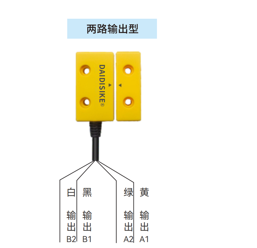
The two output channels land directly on the dual-channel monitoring input of a DQSRN or DA31 safety relay; the relay performs cross-monitoring and drives the machine contactors.
Typical Applications
Sagging or Vibrating Guard Doors
The 17 mm sensing range absorbs hinge droop, track wear and vibration that would mis-trip a tongue-operated switch.
Removable Guard Panels
No alignment precision or key slot needed — refit the panel and the coded actuator is detected anywhere inside the sensing window.
Multi-Door Production Lines
Series-connect the 2NC versions so one DQSRN or DA31 safety relay input supervises a whole row of fence doors.
Washdown & Dusty Cells
Sealed IP65 body with no plug apertures on the sensing face; IP67/IP68 builds available on custom order.
Fast-Swap Maintenance Regimes
The B version's quick-disconnect plug lets a failed switch be exchanged without opening the panel wiring.
Machine-Tool Guard Retrofits
Drop-in position monitoring for older enclosures where drilling accurate key-slot geometry is impractical.
Frequently Asked Questions
Why can't a plain magnet defeat the DX-C1 the way it defeats a reed door sensor?
Inside the DX-C1 sensor, several magnetically sensitive elements must be triggered in a defined sequence that only the paired coded actuator produces. Holding a single ordinary magnet against the housing energises the elements in the wrong pattern, so the safety outputs stay open. A basic reed-type door sensor, by contrast, closes for any sufficiently strong magnet.
How much guard-door sag or misalignment can the DX-C1 tolerate?
The sensing distance reaches up to 17 mm in both the Z and Y directions, which is what gives the switch its high misalignment tolerance. In practice that means a hinged door that has dropped a few millimetres on its hinges, or a sliding guard with a worn track, keeps actuating the switch reliably without mechanical re-adjustment — one of the main reasons to pick it over a tongue-operated interlock on older machines.
How do I wire several DX-C1 switches on a multi-door line?
Choose the 2C (two normally-closed) version and connect the switches in series, then land the loop on the dual-channel input of a DQSRN or DA31 safety relay. One relay input then monitors every door in the chain; opening any door drops both channels. Keep in mind that with series wiring the relay cannot tell you which door is open, so use the NO contact of 1C1O versions for per-door PLC indication if you need that diagnosis.
Which output configuration should I order — 2C, 1C1O or 2O?
2C (2 NC) is the standard choice for a dual-channel safety circuit. 1C1O gives one NC channel for the safety loop plus one NO contact for door-position status to a PLC. 2O (2 NO) is for non-safety position sensing only. The reed contacts are intended as pilot-duty signals into a safety relay, never as load-switching contacts — contact the factory for the contact electrical ratings before sizing any protection.
What is the difference between the DX-C1 and the DX-R1 in the same family?
Both are non-contact guard-door switches from the same DX family. The DX-C1 uses sequence-coded magnetic sensing with reed contact outputs. The DX-R1 is an RFID-coded electronic switch, offered in a uniquely-coded high-tamper-resistance version, and is the one to specify when the risk assessment demands the highest ISO 14119 coding level. For general doors where sag tolerance and simple relay wiring matter most, the DX-C1 is the more economical fit.
Does the DX-C1 hold the door closed?
No. It monitors position only — there is no locking element. If the machine coasts down after the stop signal or retains stored energy, combine the guard with a locking device: the DX-D6 RFID guard-locking switch or a DX-W2/W3/W5 solenoid door lock, optionally with the DXL mechanical door bolt.
What certifications and safety-level claims apply to the DX-C1?
The DX-C1 is CE marked (subject to the valid certificate and the models it covers). The catalogue states it is designed for use in safety circuits up to ISO 13849-1 SIL 3 / PL e / Category 4 — that is a circuit-design reference, and the level actually achieved depends on the complete circuit including the safety relay and wiring. Certification documents are available on request.
What is the MOQ, lead time and OEM policy for the DX-C1?
Small trial orders for evaluation are generally workable, and the six variants (three contact configurations × cable or quick-disconnect) share one platform, so mixed-model orders are common. For current MOQ, unit pricing, lead time and the custom IP67/IP68 sealed versions, contact the factory through the contact page — quotes are prepared per configuration.
Specs reviewed by Engineer Cai, Senior Application Engineer. See certificates.
Safety Light Curtain — Customer Cases
Real installations from DAIDISIKE clients. Click any case to view in full. Filter by scenario to quickly find a similar setup.