Actuation travel
Compression from first contact until the sensing signal changes. This is only the first part of the contact event.

Specify a pressure-sensitive contact edge around your machine contour. Choose a standard DDB or adhesive DDBT section, then confirm length, contact direction, cable exits, electrical configuration and the matching controller.
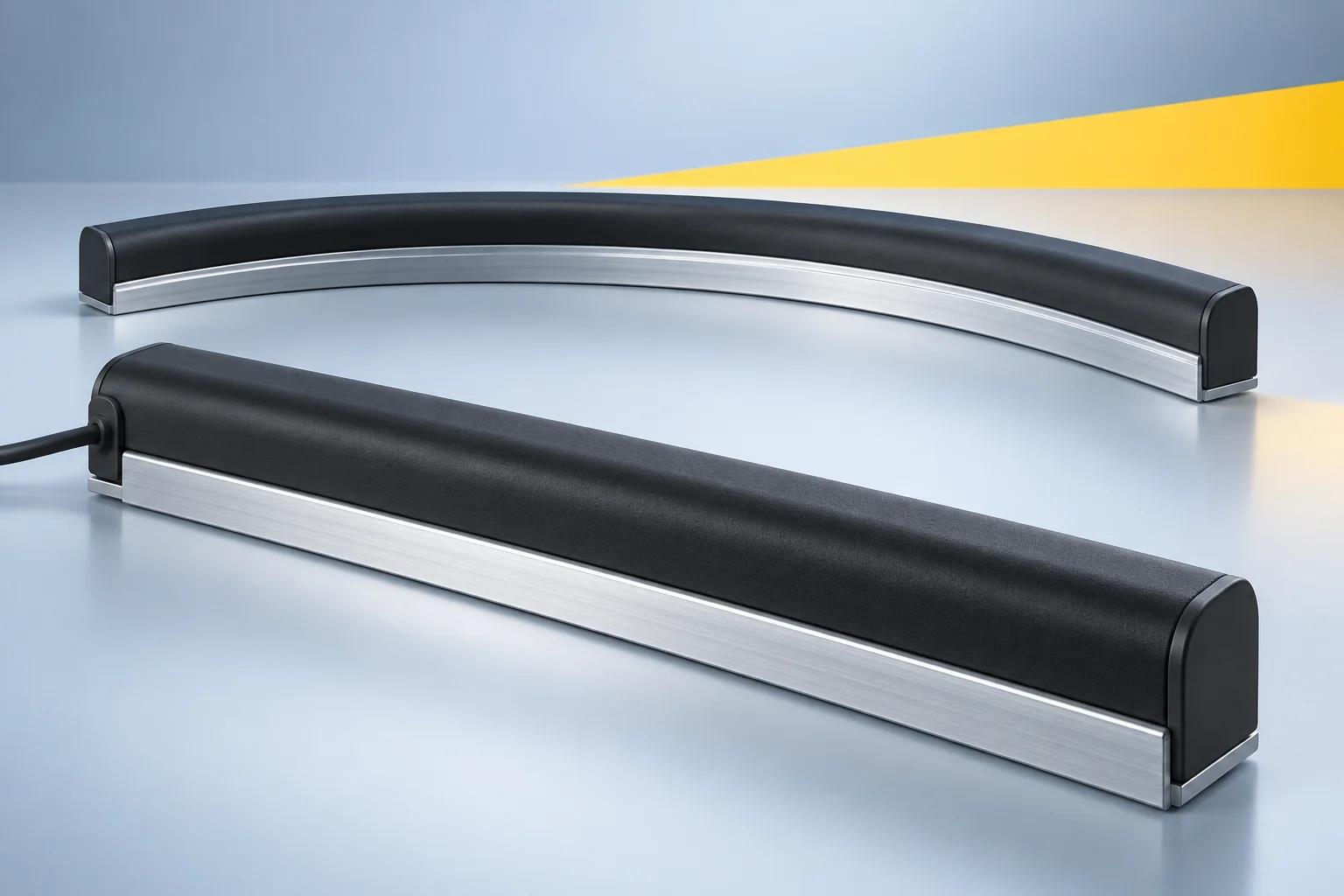
A pressure-sensitive safety edge is a contact-sensing device, not a non-contact distance sensor. When pressure changes the sensing state, the compatible controller and final stopping elements must bring hazardous motion to the required safe condition.
The selected profile is compressed in its intended sensing direction.
The matched input circuit evaluates the state and required diagnostics.
The stop or safe reversing function acts through the final elements.
Stopping travel and remaining compression are checked on the machine.
Compression from first contact until the sensing signal changes. This is only the first part of the contact event.
Additional compression after actuation. Select and validate it against motion after detection, tolerances, temperature and elastic recovery.
| Selection point | JH-PSE | DDB / DDBT |
|---|---|---|
| Product scope | 7 main profiles and 37 extension profiles | Custom range: 5 standard and 6 adhesive sections |
| Listed length | Main: 30-300 cm; extension: 20-300 cm | 200-3000 mm; custom options |
| Mounting | Profile-matched bases and confirmed section drawings | DDB standard mounting / DDBT adhesive mounting |
| Electrical selection | R / K; main and extension cable data differ | 2K / 4K / 2R; custom interface defined by order |
| Best starting point | Compare published main-range dynamics or extension profile geometry | Start with the machine contour, mounting face and custom interface |
Need the other range? Explore JH-PSE Safety Edges. A similar outside shape does not establish identical actuation, wiring or stopping performance.
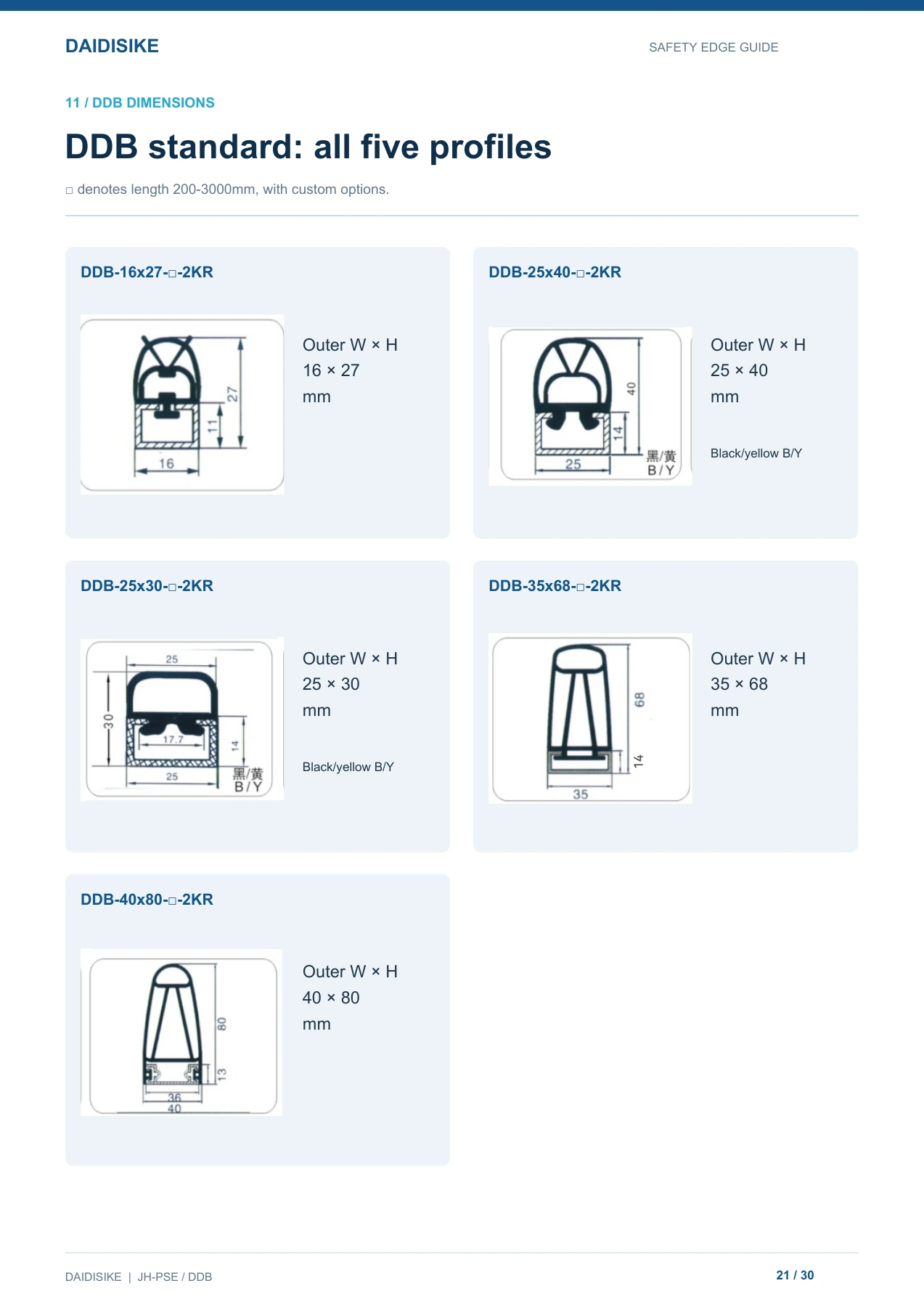
DDB covers compact through larger contact-edge sections. Use the outer width and height to shortlist an installation envelope, then confirm the sensing direction, mounting arrangement, ends and electrical configuration. Section size alone does not establish actuation force or stopping performance.
| Listed model pattern | Outer W × H | Section notes |
|---|---|---|
| DDB-16x27-□-2KR | 16 × 27 | Standard DDB section |
| DDB-25x40-□-2KR | 25 × 40 | Black / yellow (B/Y) shown in the guide |
| DDB-25x30-□-2KR | 25 × 30 | Black / yellow (B/Y) shown in the guide |
| DDB-35x68-□-2KR | 35 × 68 | Standard DDB section |
| DDB-40x80-□-2KR | 40 × 80 | Standard DDB section |
The square □ in these catalog patterns denotes length, listed as 200-3000 mm with custom options. Replace it with the confirmed ordered length. The illustrated 2KR suffix is an example, not the only order configuration.
Ask for the section/base drawing, actual overall length, active coverage, inactive ends, mounting details, cable exit and sealed-end arrangement. A rubber profile description by itself is not sufficient for mechanical design or safe integration.
DDBT provides adhesive mounting options where the mounting face and application support that method. Confirm the surface preparation, adhesive process, environmental suitability and cable support for the exact assembly rather than assuming adhesive replaces all mechanical-design checks.
| Listed model pattern | Section W × H | Drawing / order distinction |
|---|---|---|
| DDBT-25x15-□-2KR | 25 × 15 | Section A: arch cavity; adhesive backing, black / red |
| DDBT-12x12-□-2KR | 15 × 12 in the section drawing | Model name and drawing differ. Confirm the approved section before ordering. |
| DDBT-25x15-□-2KR | 25 × 15 | Section B: circular core; distinguish from Section A on the order drawing |
| DDBT-15x8-□-2KR | 15 × 8 | Confirm mounting face against the section drawing |
| DDBT-20x15-□-2KR | 20 × 15 | Confirm mounting face against the section drawing |
| DDBT-7x4-□-2KR | 7 × 4 | Confirm mounting face against the section drawing |
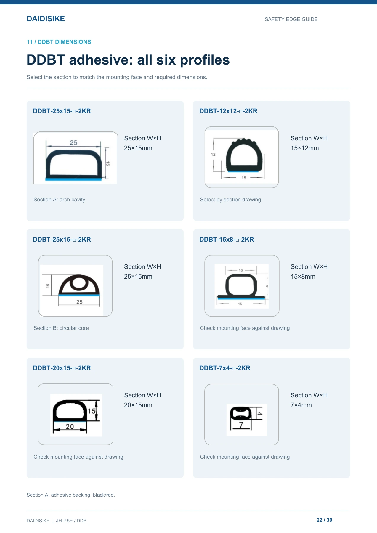
The guide identifies Section A as adhesive-backed and black/red. It does not establish one common adhesive specification or a single color choice for all six sections. Confirm the exact supplied variant.
Send your mounting-face drawingA custom safety edge must follow the machine contour and respond from the actual contact direction. The guide illustrates external, lateral and internal edges, together with external, lateral and internal curves. Each needs an agreed active area, end treatment, mounting arrangement and cable route.
Provide the overall protected length, straight and curved sections, minimum curvature, corner and joint positions. Mark inactive ends and any gaps that could leave a hazardous contact point uncovered.
Show the contact direction and angle, moving-part speed, load, available compression space and travel after actuation. Request the selected assembly's relevant actuation and stopping-reserve information.
Define sealed ends, cable exits, cable length and connector, mounting method, electrical configuration, controller and reset behavior. Agree the order drawing before manufacturing.
DDB-16x27-200-2KRDDB / DDBT: standard / adhesive range. 16x27: section dimensions; always check the drawing. 200: length in mm. 2K / 4K / 2R: cable/resistor configuration. R / S: standard / special shape in its separate field.
The custom range lists IP65 protection and 200-3000 mm lengths with custom options. The supplied DDB/DDBT section does not publish a universal response time, actuation force, overtravel or minimum bend radius. Do not substitute JH-PSE values.
The guide describes DDB as a custom dual-output range. This is not a universal OSSD, PNP or NPN specification. The output type, channel configuration and terminal functions must be agreed for the delivered assembly and compatible controller.
| Configuration | Meaning | What still needs confirmation |
|---|---|---|
| 2K | Two-core without a resistor | Controller input principle, cable ends and approved monitoring method |
| 4K | Four-core without a resistor | Conductor functions, channel arrangement and approved circuit |
| 2R | Two-core with a resistor | Exact resistance, power, position and controller compatibility |
PDF page 24 shows two edge-input groups connected to a DA31 safety relay, each with a 5.6 kΩ end-of-line resistor, and a PLC status interface. It illustrates a system concept, not a terminal-level installation diagram.
The three edge icons per group do not establish a permitted maximum quantity. Use the supplied DA31 wiring diagram to confirm edge count, terminals, power supply, termination, diagnostics, reset and the final stopping elements.
View the DA31 safety relay moduleThe guide shows parallel and daisy-chain connection layouts. A parallel NO circuit can respond when any edge is actuated, but that alone does not prove that an open branch is detected.
For a daisy-chain arrangement, confirm the return conductors, resistor position and permitted edge quantity. Use only the controller-approved layout and verify the required fault detection during commissioning.
The DA31 5.6 kΩ example must not be mixed with JH-PSE 1.2 kΩ / 8.2 kΩ configurations. Obtain the exact supplied wiring diagram before connection. The edge, controller, final switching devices and machine stopping behavior must be assessed together; a series name or relay alone does not establish an achieved PL, SIL or safety category.
The following illustrations explain possible contact-detection locations. They are conceptual application visuals, not photographs of the ordered models or validated installation drawings.
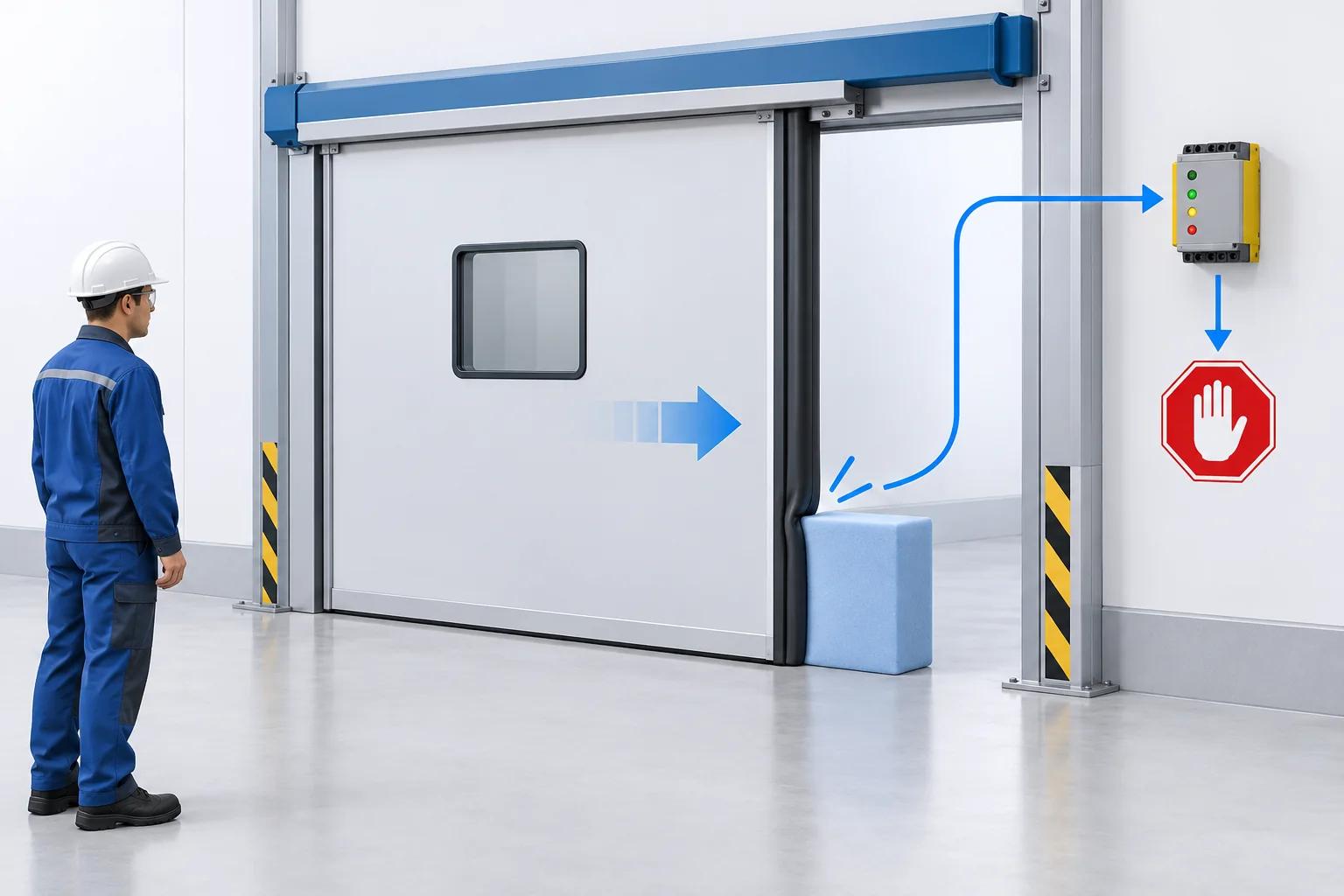
Place contact sensing along the hazardous closing boundary. Check hinges, overlaps, joints and inactive ends. The risk assessment must determine whether stopping, safe reversing or additional protective measures are required.
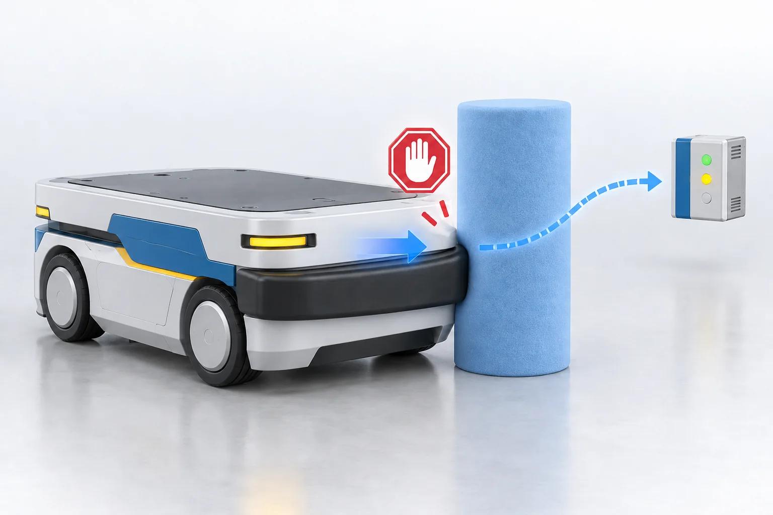
Follow the vehicle contact perimeter with a suitable profile. Validate maximum speed and load, actual braking performance, contact direction and remaining compression; an attractive bumper shape does not prove adequate protection.
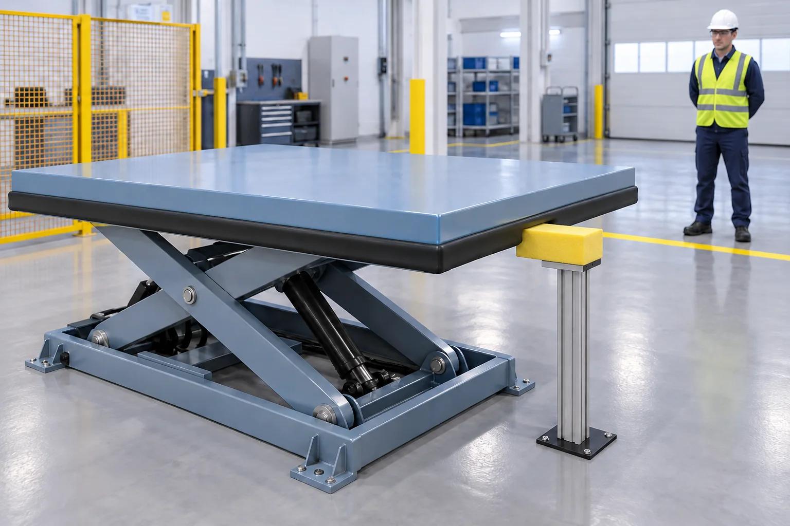
Address accessible contact edges on moving covers and lifting equipment. Check low contact points and bypassable gaps, and provide the required guarding. Never enter beneath an unprotected lifting mechanism.
Use suitable test tools or foam objects, not fingers or body parts exposed to crushing. Contact protection may need to work alongside guards, interlocks or non-contact detection.
Qualified personnel must work to the approved machine and controller drawings. Isolate power before wiring, and do not cut open a delivered sealed edge.
An always-active signal can indicate preload, damage, a short circuit or an incorrect resistor. No actuation can indicate an inactive zone, unsuitable force direction, an open circuit or an input mismatch. Intermittent faults require checks of flexing cables, joints, sealing, mounting and vibration. Never bridge a safety input to keep a machine running.
30-page English guide. DDB/DDBT selection and dimensions: pages 20-23; DA31 connection concept: pages 24-25. Includes both ranges and installation/commissioning guidance. Preview opens the original PDF in a new tab; download saves the same document. Use the approved order-specific drawing and controller instructions for installation.
Shared 30-page English catalogue for JH-PSE profiles and DDB / DDBT assemblies. Match each table and drawing to the exact series; confirm the supplied edge and evaluation controller before installation.
Confirm the document and CAD file match your exact ordered version before installation or mechanical design. Contact us if your model is not listed.
For a useful quotation, include the mechanical drawing and the controller details, not just “a safety edge.” This allows the profile, sensing coverage and electrical configuration to be checked together.
| Project detail | What to provide |
|---|---|
| Product / profile | DDB or DDBT model; Section A / B where applicable; confirmed dimensions |
| Dimensions and coverage | Overall length, active coverage, inactive ends, mounting space, curve radius and corner positions |
| Motion and contact | Hazardous edge, actuation direction, maximum speed / load and post-actuation travel |
| Electrical interface | Controller model and diagram; cores, cable ends, resistor / power, output functions and connector |
| Installation and environment | Base or adhesive mounting, fasteners, seals, cable support and environmental conditions |
| Required documents | Approved assembly drawing, order-specific wiring diagram, inspection information and operating instructions |
DDB is the standard custom range; DDBT is the adhesive-mounting range. The guide lists five DDB standard sections and six DDBT adhesive sections. Select the section and mounting face using the drawings, then confirm the mounting method, overall length, ends, cable arrangement and control interface on the order-specific drawing.
No such universal output is specified in the supplied guide. The range is described as custom dual-output, but output type, channel configuration and terminal functions must be defined for the ordered assembly. Do not assume OSSD, PNP, NPN, a direct PLC safety interface or a particular pinout from the series name.
The supplied guide names the section DDBT-12x12 but shows a 15 × 12 mm section. This discrepancy is retained openly rather than silently changing the model or dimensions. Ask DAIDISIKE to confirm the approved section drawing and installation dimensions before ordering or machining the mounting surface.
Do not identify them by the 25 × 15 mm size alone. The guide shows Section A with an arch cavity and Section B with a circular core under the same model designation. Reference the selected section drawing, cavity geometry, mounting face and cable arrangement on the quotation and purchase order.
2K means two-core without a resistor; 4K means four-core without a resistor; 2R means two-core with a resistor. The DA31 illustration shows two edge-input groups, each with a 5.6 kΩ end resistor. This is a connection concept, not confirmation that every DDB/DDBT configuration connects unchanged. Use the supplied order-specific DA31 or controller diagram to verify resistor, permitted quantity, supply, terminals and reset behavior.
No. Contact changes the sensing state; a compatible controller and the machine stopping system must then respond. Controller delay, switching time, inertia, speed and load contribute to the motion after actuation. Measure the complete machine stopping performance and verify that the selected profile provides sufficient usable compression and an appropriate safety margin.
Do not cut open a sealed edge. Order the required length, contour, cable exits and sealed ends. Multiple-edge connections must follow the supplied controller-approved drawing, including termination, return conductors and permitted edge quantity. A parallel NO-contact arrangement does not by itself prove that every branch is monitored for an open circuit.
Send the full model or required section drawing, overall length, protected contour, force direction, mounting space, speed and load, measured or expected stopping travel, cable exits and connector requirements. Identify the controller and its required resistor and input arrangement. Request an order-specific drawing, wiring diagram, inspection information and operating instructions.
Product data and source drawings: the DAIDISIKE 30-page English JH-PSE / DDB safety edge guide. Figures remain range- and model-specific. Confirm the current ordered assembly, electrical compatibility and complete safety function with qualified personnel. No third-party certification or achieved machine safety level is implied by this product overview.