
D3J-03xx Series Modbus RTU Digital I/O ModulesD3J0302 · D3J0304 · D3J0308 · D3J0312
Read sensors and switch loads from the same RS-485 board. One combined input/output platform, four sizes — from a 2-in/1-out edge node to a 12-in/8-out panel concentrator — so every drop on your Modbus RTU network carries exactly the I/O it needs.
- 2/1 · 4/2 · 8/4 · 12/8 isolated input/output channels
- Relay (AC 0-220V, 8A) or transistor (DC 12-48V, 8A) outputs
- Local input-linked control + BRKFLG emergency brake
- 5 jog/delay timing modes, optional PWM/PTO pulse channels
- 2 kV EFT immunity — double the IEC 61000-6-2 industrial level
One Board Instead of Two: the Case for Combined I/O Drops
Most RS-485 remote I/O forces a choice: buy an input module and an output module, wire both, and give both a bus address. On a real machine the signals and the actuators sit centimetres apart, so the D3J-03xx puts both on one board — the host reads limit switches and e-stops with function code 0x02 and drives contactors through the DOUTnDV registers over the same twisted pair, one address per station.
- Fewer nodes, simpler polling. A two-sensor, one-valve station is one device, one power feed, one address — not two of each.
- Local interlocks that outlive the network. Output n can follow input n and the BRKFLG brake forces outputs to a preset safe state on a limit/e-stop trigger, both inside the module at ~20 ms — no host in the loop.
- Load flexibility per order code. The same part number covers AC (relay contacts) and DC (open-drain FET with 10A flyback diode) worlds; PWM/PTO pulse channels are an ordering digit away.
- Isolation everywhere it counts. RS-485, all inputs and all outputs are isolated from internal logic (type-tested DC 1000V/60 s; transistor outputs < 130V working).
RS-485 Wiring Topology — Inputs In, Outputs Out, One Pair Back
Example load assignments for illustration. When several modules share one bus, give each a unique slave address (1-247) and plan bus termination per your installation practice.
Model Selection Table — Match the Station, Not the Catalog
| Model | Inputs / outputs | Dimensions (L×W×H) | Screw terminals | Default order code | Product ID | Best fit |
|---|---|---|---|---|---|---|
| D3J0302 | 2 in / 1 out | 54 × 88 × 59 mm | 8 screw terminals | D3J0302M111 | 0x3302 | Single-device edge node: one sensor pair, one actuator |
| D3J0304 | 4 in / 2 out | 72 × 88 × 59 mm | 14 screw terminals | D3J0304M111 | 0x3304 | Small machines: 3-4 signals, 1-2 loads (e.g. motor fwd/rev) |
| D3J0308 | 8 in / 4 out | 107 × 88 × 59 mm | 26 screw terminals | D3J0308M111 | 0x3308 | Mid-size machines and distributed stations (5-8 in, 3-4 out) |
| D3J0312 | 12 in / 8 out | 158 × 88 × 59 mm | 44 screw terminals | D3J0312M111 | 0x3312 | Whole-panel control / low-cost PLC-style I/O concentration |
All dimensions carry a ±5% tolerance; terminal pitch is 5.08 mm across the series. Ordering code D3J03[aa]R[b]T[c]M[ddd] — [aa] is the input count (02/04/08/12); the M[ddd] digits select output type (1 = relay, 2 = transistor), pulse-output availability (3 = DO0 high-speed, 4 = DO0+DO1 high-speed) and wireless (2 = 2.4GHz MODBUS-OTA). The "XS" suffix orders the input-reinforced version for frequent-EFT sites.
Output ratings at a glance
| Output type | Normal rating | Absolute maximum | Isolation (normal) | Notes |
|---|---|---|---|---|
| Relay (default) | DC 30V or AC 0-220V, 8A | DC 30V or AC 0-220V, 8A | < 250V | NC/COM/NO dry contact; mechanical life > 100,000 ops (> 10,000 under heavy load) |
| Standard transistor | DC 12-48V, 8A | DC 55V, 10A | < 130V | Open-drain; built-in 10A flyback diode drives inductive loads directly |
| High-speed transistor | DC 12-24V, 8A | DC 40V, 10A | < 130V | Required for fast PWM (FPWM0PRD/FPWM0DTY) and PTO pulse trains |
Loads above 8A, or AC above 220V, should be switched through an external contactor sized for the load. Transistor outputs may briefly mis-conduct for ~100 ms during power transitions — power the module on before the output side and off after it.
Shared Specifications (All Four Models)
| Function | Combined digital input acquisition + digital output control on one Modbus RTU / RS-485 slave |
|---|---|
| Protocol | Modbus RTU (primary) over half-duplex RS-485; Modbus ASCII and AT commands also supported; optional 2.4GHz wireless MODBUS-OTA |
| Default communication | 9600 bps, 8 data bits, even parity, 1 stop bit, slave address 0x02 |
| Configurable range | Baud 300-115200 bps; parity none/odd/even; stop bits 1/1.5/2; address 1-247 |
| Function codes | 0x02 read discrete inputs; 0x03/0x06/0x10 holding registers (DOUTnDV output drive); 0x04, 0x16, 0x17, 0x11 also supported |
| Supply | DC 11-28V, current < 1500 mA, ripple < 1 Vp-p; reverse-polarity / overcurrent / surge / load-dump protected; DC 250V 3000 mA slow-blow fuse |
| Inputs | Threshold ≈ 3V; stress DC 0-30V normal, DC 50V absolute maximum; per-channel DINnCNT edge counter (rolls over at 65535) and DINnFLT debounce filter savable through power loss |
| Local output logic | Direct drive via DOUTnDV (polarity invert, coil force); 5 jog/delay modes; input linkage (output n ← input n); BRKFLG emergency brake at highest priority — all without host intervention, typ. 20 ms |
| Pulse outputs | Up to 2 high-speed channels: standard PWM speed control or PTO stepper drive (segmented PGM program); fast PWM via FPWM0PRD / FPWM0DTY |
| Isolation | RS-485, all inputs and all outputs isolated from internal logic (relay < 250V, transistor < 130V working; DC 1000V/60 s type test, transistor DC 250V/60 s). USB and analog inputs not isolated |
| EMC | ESD 4 kV (A); EFT 2 kV/5 kHz/2 min (A), 4 kV no permanent damage (C); surge 1 kV to ground (C) |
| Creepage / clearance | > 6.5 mm measured (req. > 6 mm) / > 2.2 mm measured (req. > 2 mm), pollution degree 3 |
| Bonus channels | 2 analog inputs + 5V/100mA sensor supply on every board (internal leads) |
| Environment | Operating −20 to 60 °C; storage −40 to 85 °C |
| Config protection | Safety-lock register: write ASCII "UL" before each sensitive write; auto re-locks after every write |
Top of the Series — D3J0312, 12-in/8-out
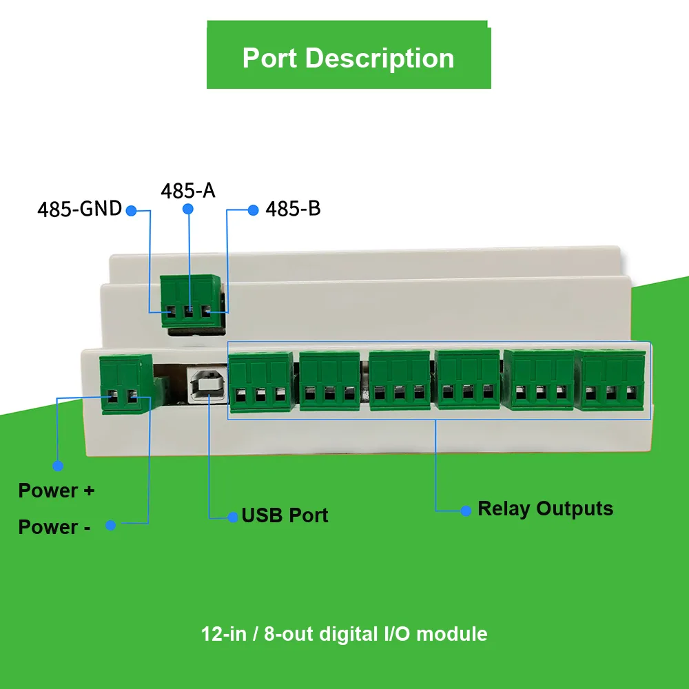
One 158 mm board with 44 screw terminals reads 12 field signals and drives 8 loads — replacing the base unit, expansion cards and backplane a small PLC would need for the same 20 points, while local linkage and BRKFLG keep the panel safe if the bus drops.
Typical Applications
Single-Device Edge Nodes
D3J0302 reads a start/stop or e-stop and drives one motor or solenoid; local linkage keeps the stop working if RS-485 is interrupted.
Forward/Reverse Motor Control
D3J0304 drives fwd/rev contactors while its inputs read both travel limits, combining with the brake function for in-position stops.
Pump Stations & Water Treatment
D3J0308/0312 read level floats and fault contacts and stage multiple pumps or valves, with jog/delay run-on timing that survives a host outage.
Whole-Panel Concentration
D3J0312 reads 12 panel signals and drives 8 contactors as a low-cost PLC-style node — one address, one poll, one power feed.
Greenhouse Zone Control
The 5V sensor supply powers a moisture probe, analog inputs read it, and outputs drive irrigation or fans with automatic delay shutoff.
PWM Heating & Stepper Drive
High-speed transistor versions add fast PWM for heaters and PTO pulse trains for steppers alongside the ordinary I/O channels.
Frequently Asked Questions
What is the difference between D3J0302, D3J0304, D3J0308 and D3J0312?
All four share the same ASIC-based Modbus RTU / RS-485 combined input/output design and differ only in channel count and board size: D3J0302 is 2-in/1-out (54 mm board, 8 terminals), D3J0304 is 4-in/2-out (72 mm, 14 terminals), D3J0308 is 8-in/4-out (107 mm, 26 terminals) and D3J0312 is 12-in/8-out (158 mm, 44 terminals). Protocol, register map, supply range, output ratings and local-logic features are identical across the series.
Should I choose relay or transistor outputs?
Relay outputs (the M111 default) switch DC 30V or AC 0-220V at 8A with real NC/COM/NO contact isolation — the choice for 220V AC contactors, lamps and heaters, with mechanical life over 100,000 operations. Transistor outputs are open-drain, DC 12-48V at 8A, with a built-in 10A flyback diode, so solenoids and DC motors connect directly with no external suppression diode — and they are required if you want the PWM/PTO pulse function. The choice is one digit in the M[ddd] order code, not a different product.
Can the outputs keep working if the RS-485 bus or the PLC goes down?
Yes — two local mechanisms run entirely inside the module. Input linkage ties output n to input n so the output follows its own input with no host traffic, and the emergency-brake function (BRKFLG) forces outputs to a preset safe state the moment a designated limit or e-stop input trips, at the highest priority. Both respond in a typical 20 ms, so a cut cable or a crashed host does not leave an actuator stuck on. Note these are convenience features, not a certified safety function.
What do the jog/delay modes and pulse outputs do?
Each output supports 5 jog/delay timing modes: once the trigger condition is met the channel closes and drops out automatically after a configurable delay — covering pump run-on, valve pulse dosing and fan post-purge without ladder code. Separately, up to 2 channels can be ordered as high-speed transistor outputs providing PWM speed control (FPWM0PRD period / FPWM0DTY duty) or PTO pulse trains for stepper drive.
Can I treat the input linkage or BRKFLG brake as a machine safety function?
No. These are non-safety parts — no D3J-03xx output is an OSSD, and linkage and brake are ordinary firmware features with a ~20 ms typical response. For e-stop circuits, guard interlocks or light-curtain monitoring, use a DQSRN or DA31 safety relay for the safety circuit, and let the D3J-03xx handle ordinary automation I/O.
How do these modules integrate with an existing PLC, HMI or SCADA?
As standard Modbus RTU slaves: inputs are read with function code 0x02, outputs are driven through the DOUTnDV holding registers with 0x03/0x06/0x10, and 0x04/0x16/0x17/0x11 are also supported. Defaults are 9600 bps, 8 data bits, even parity, 1 stop bit, address 0x02 (range 1-247, baud 300-115200 bps). Modbus ASCII suits touch panels, AT commands suit quick bench tests, and the built-in USB port doubles as a USB-to-serial converter for commissioning from a laptop.
What about MOQ, lead time, wireless and custom configurations?
Output type, pulse-output availability and the 2.4GHz MODBUS-OTA wireless link are all selected by the M[ddd] digits of the ordering code at order time (e.g. D3J0302M231 = high-speed transistor with fast PWM), and the input-reinforced XS suffix hardens the input stage for frequent-EFT sites. For current MOQ, pricing and lead time per configuration, contact the factory through the contact page — quotes are prepared per order code. Certification documents are available on request.
Specs transcribed from factory documentation and reviewed by Engineer Cai, Senior Application Engineer. See certificates.