
D3J-01xx Series Modbus RTU Digital Input ModulesD3J0104 · D3J0108 · D3J0116 · D3J0128
One pure-input platform, four channel counts. Put 4, 8, 16 or 28 fully isolated digital signals onto a single RS-485 / Modbus RTU node — sized to the point count of each location instead of hauling every wire back to one big card.
- 4 / 8 / 16 / 28 fully isolated inputs per module
- Modbus RTU slave, address 1-247, 300-115200 bps
- Per-channel edge counters and 1-65535 ms debounce filters
- 2 kV EFT immunity — double the IEC 61000-6-2 industrial level
- USB port doubles as a USB-to-serial converter
Why Expand Inputs over Modbus RTU Instead of Pulling Cable
Every extra dry contact, limit switch or breaker auxiliary you hard-wire to a central PLC costs a dedicated copper run, a terminal, and an input card point. The D3J-01xx approach digitises signals where they occur: a small module sits in the machine's own junction box, reads its local points, and only a twisted RS-485 pair goes back to the control room. One function-code 0x02 poll returns every channel of a module in a single reply (≤ 25 ms), and up to 247 addresses fit on the bus.
- Less copper, shorter low-level runs. Contact wiring stays inside the cabinet or machine; only the bus travels.
- Failure containment. A fault at one drop takes down 4 or 8 channels, not a 28-point central card.
- Signal hygiene built in. All inputs and the RS-485 port are galvanically isolated (type-tested DC 1000V/60 s), so ground-potential differences between buildings never ride the bus.
- Host offload. Debounce filters and rising-edge counters run in module hardware — no debounce timers or edge-detect rungs in the PLC.
RS-485 Bus Topology — Mixing the Four Models on One Pair
Example addresses shown for illustration; every module ships at 0x02 and is re-addressed after a SAFELCK unlock. When connected over USB a module answers at fixed address 0x01 and its RS-485 port switches to master mode — handy for bench commissioning.
Model Selection Table — Four Channel Counts, One Platform
| Model | Isolated inputs | Dimensions (L×W×H) | Screw terminals | Indicator LEDs | Product ID | Best fit |
|---|---|---|---|---|---|---|
| D3J0104 | 4 fully isolated | 54 × 88 × 59 mm | 8 screw terminals | 4 input + 1 power | 0x3104 | Scattered points — a few signals per location, many locations |
| D3J0108 | 8 fully isolated | 72 × 88 × 59 mm | Contact factory | Contact factory | 0x3108 | One machine or a small-to-medium cabinet (5-8 points) |
| D3J0116 | 16 fully isolated | 107 × 88 × 59 mm | Contact factory | Contact factory | 0x3116 | Mid-size cabinet or line section (9-16 points) |
| D3J0128 | 28 fully isolated | 158 × 88 × 59 mm | Contact factory | 28 input + 1 power | 0x3128 | High-density central acquisition (approx. 20+ points in one panel) |
All dimensions carry a ±5% tolerance; terminal pitch is 5.08 mm across the series. Ordering code format D3J01[aa]R[b]T[c]M[d] — [aa] is the channel count (04/08/16/28), the M digit selects the wireless option (1 = RS-485 only, default; 2 = 2.4GHz MODBUS-OTA), and the "XS" suffix orders the input-reinforced version for frequent-EFT sites.
Selection logic in one paragraph
Distribute small, consolidate large. Scattered points (a gate here, a pump there) favour several D3J0104 units close to the signals; a single machine or small cabinet with 5-8 points is the natural D3J0108; 9-16 points concentrated in a mid-size panel call for D3J0116; and when a switchgear room concentrates twenty-plus status contacts, one D3J0128 gives the lowest cost per point and only one node to poll. If any point must also switch something, step over to the D3J-03xx combined input/output series instead.
Shared Specifications (All Four Models)
| Function | Pure digital input acquisition — no relay or transistor outputs on any D3J-01xx model |
|---|---|
| Protocol | Modbus RTU (primary) over half-duplex RS-485 (A/B differential pair); Modbus ASCII and AT commands also supported; optional 2.4GHz wireless MODBUS-OTA |
| Default communication | 9600 bps, 8 data bits, even parity, 1 stop bit, slave address 0x02 |
| Configurable range | Baud 300-115200 bps; parity none/odd/even; stop bits 1/1.5/2; address 1-247 |
| Function codes | 0x02 read discrete inputs, 0x04, 0x03, 0x06, 0x10, 0x16, 0x17, 0x11 report device ID; exception codes 0x01-0x04 returned on errors |
| Supply | DC 11-28V, current < 1500 mA, ripple < 1 Vp-p; reverse-polarity / overcurrent / surge / load-dump protected; DC 250V 3000 mA slow-blow fuse |
| Inputs | Threshold ≈ 3V; stress DC 0-30V normal, DC 50V absolute maximum; typical response 20 ms |
| Per-channel features | DINnCNT rising-edge counter (≤ 5 Hz, rolls over at 65535, clearable); DINnFLT filter 1-65535 ms (0 = off), savable via MODESAVE = "MS" |
| Isolation | All digital inputs and RS-485 port isolated from logic (< 250V working; DC 1000V / 60 s type test). USB port and analog inputs are not isolated |
| EMC | ESD 4 kV (Criterion A); EFT 2 kV/5 kHz/2 min (A), 4 kV no permanent damage (C); surge 1 kV to ground (C) |
| Creepage / clearance | > 6.5 mm measured (req. > 6 mm) / > 2.2 mm measured (req. > 2 mm), pollution degree 3 |
| Bonus channels | 2 analog inputs (1 mV/bit, ≈10-bit, typ. 3% accuracy) + 5V/100mA sensor supply (internal leads, not isolated) |
| Environment | Operating −20 to 60 °C; storage −40 to 85 °C |
| Config protection | SAFELCK register (0x000E): write ASCII "UL" (0x554C) before each sensitive write; auto re-locks after every write or on any bus error |
High-Density End of the Series — D3J0128
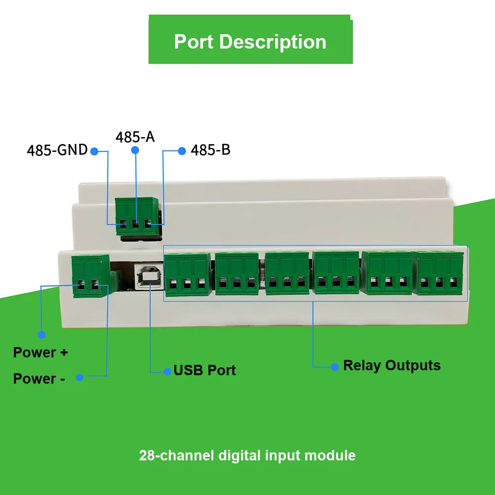
The 28-channel D3J0128 concentrates a whole cabinet onto one slave address: a single function-code 0x02 poll returns all 28 discrete inputs in one ≤ 25 ms reply, and per-channel LEDs let an electrician verify every field wire at the terminal strip before any host software exists.
Typical Applications
Distributed Machine Status
4/8-channel drops at each machine read limit and proximity switches; edge counters return cycle totals on the same poll as the status bits.
Switchgear & Panel Monitoring
Breaker auxiliaries, door contacts and fault dry contacts consolidated by a 16/28-channel unit — 2 kV EFT margin suits contactor-dense cabinets.
Data Center / Equipment Rooms
Leak detectors, door contacts, fire and UPS alarms aggregated to one RS-485 address, with per-channel filters suppressing contact chatter.
Energy, PV & Storage Stations
Status and alarm contacts across combiner boxes and storage cabinets, where full isolation matters next to inverters and heavy switching.
Municipal Scattered Points
Pump stations, gates and manhole covers with differing ground references; the optional 2.4GHz MODBUS-OTA version removes cabling between distant points.
Legacy Retrofit
Old machines exposing only dry contacts join a Modbus network with one small module; the USB port verifies signals from a laptop before SCADA exists.
Frequently Asked Questions
What is the difference between D3J0104, D3J0108, D3J0116 and D3J0128?
All four are the same D3J-01xx pure-input design — fully isolated Modbus RTU / RS-485 digital input modules built around a dedicated ASIC — and differ only in channel count and board length: D3J0104 has 4 inputs (54 mm board), D3J0108 has 8 inputs (72 mm), D3J0116 has 16 inputs (107 mm) and D3J0128 has 28 inputs (158 mm). Register map, protocol, supply range and EMC ratings are shared, so firmware and host code written for one model works across the series.
Can I mix different D3J-01xx models on the same RS-485 bus?
Yes. Every module is a standard Modbus RTU slave with a configurable address from 1 to 247 (0x01-0xF7), so a 4-channel unit at a remote pump, an 8-channel unit at a machine and a 28-channel unit in the main panel can share one twisted pair and be polled by the same PLC, HMI or SCADA master. Keep each address unique and stay within your RS-485 transceiver's electrical loading limits.
Do D3J-01xx modules have any relay or transistor outputs?
No. The whole D3J-01xx series is pure input — the modules only read digital signals (dry contacts, limit switches, proximity and photoelectric switches) and report them upstream. If you need outputs on the same board, use the D3J-03xx combined input/output series (2-in/1-out up to 12-in/8-out); if you need output-only modules, see the D3J-02xx serial output family.
What are the default communication settings, and can they be changed?
Factory default is Modbus RTU at 9600 bps, 8 data bits, even parity, 1 stop bit, slave address 0x02. Baud rate is selectable from 300 to 115200 bps, parity none/odd/even, stop bits 1/1.5/2, address 1-247. Sensitive registers are protected by the SAFELCK mechanism: write ASCII "UL" (0x554C) to register 0x000E before each change — the lock re-arms automatically after every write and whenever a bus error is detected.
How do the per-channel edge counters and input filters work?
Each input channel has its own DINnCNT rising-edge counter (pulse frequency up to 5 Hz, rolls over at 65535, clearable by write) and its own DINnFLT debounce filter adjustable from 1 to 65535 ms (0 = off), savable to non-volatile memory by writing MODESAVE = "MS". Debouncing and cycle counting therefore happen in the module's hardware instead of consuming PLC scan time.
Can D3J-01xx inputs be used in a machine safety circuit (e-stop, light-curtain OSSD)?
No. These are non-safety parts: inputs trip at an ordinary ~3V threshold with basic isolation only, and there is no dual-channel safety logic. For emergency-stop, guard-interlock or OSSD monitoring, use a DQSRN or DA31 safety relay for the safety circuit, and keep the D3J-01xx for status monitoring.
What is the MOQ, lead time and OEM policy for the D3J-01xx series?
Small trial orders are generally workable for evaluation, and the four models share one platform so mixed-model orders are common. For current MOQ, unit pricing, lead time, the 2.4GHz MODBUS-OTA wireless option and the input-reinforced XS variant, contact the factory through the contact page or export hotline — quotes are prepared per configuration. Certification documents are available on request.
Specs transcribed from factory documentation and reviewed by Engineer Cai, Senior Application Engineer. See certificates.