
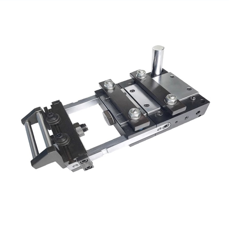
A punch press feeder has one job: deliver the strip into the die, the same distance, every stroke, in time. Get that right and the die makes good parts. Get it wrong and you chase short feeds, slip and scrap. The pneumatic air feeder is the simplest, cheapest tool for that job — an intermittent-grip device that pushes the coil forward using pneumatic feed power. Mechanical actuation can avoid electrical control power; an electric valve cannot. But “simple” does not mean “forgiving.” You still have to size it to the die, the press and the material. Evaluate the feeder, straightener and decoiler combination together before selecting a model. For a new purchase use this sizing guide; if an installed feeder has started losing pitch, use the slip and feed-drift diagnostic checklist.
Step 1 — Feed length must equal the die pitch
Start with the die, not the feeder. On a progressive die the strip advances by the progression, also called the pitch — the center-to-center distance from one station to the next. The feeder’s feed length per stroke must equal that pitch exactly. This is the single most important number, because part-to-part accuracy is set by feed precision, not by press tonnage. A 200-ton press feeding 0.3 mm short still makes garbage.
So measure your progression and confirm it sits inside the feeder’s adjustable feed-length band. The DAIDISIKE A50, A100 and B150 give an adjustable feed length of 50–250 mm, which covers the common small-part pitches you see in terminal, connector, contact and bracket stamping. If your progression is longer than the band, that is your first signal that an air feeder may not be the right tool and a servo feeder should be on the table.
Step 2 — Understand the feed window before you talk speed
Speed on an air feeder is not about how fast the cylinder can move. It is about how much time the press gives you to feed. A press stroke is 360° of crank rotation: top dead center (TDC) at 0°, bottom dead center (BDC) at 180°, and the return from 180° back to 360°. The strip can only advance while the die is open — clear of the strip. Feeding into a closing die wrecks the strip and the die both. So every feed has to start and finish inside that open-die “feed window.”
Establish the available feed angle from the actual tooling clearance, pilot engagement and press timing. A 180° allowanceappears in the Rapid-Air manual as guidance for its feeds; it is not a universal crank-angle setting for every die. The following table identifies states to verify, not commissioning angles.
| Crank angle | What is happening | Feed? |
|---|---|---|
| 0° (TDC) | Ram at top, die fully open | Confirm tool and pilot clearance |
| Documented feed interval | Tooling and pilots clear the strip | Complete feed and settle before interference |
| 180° (BDC) | Punch through material, die closed | Strip must be stopped & piloted |
| 180–360° | Ram returns, die reopens | Sequence per the feeder and die instructions |
Step 3 — Match feeder SPM to press SPM, with headroom
Two conditions have to hold at once. The feeder’s strokes-per- minute capability must meet or exceed the press SPM, and the feed-plus-settle has to fit inside the open-die dwell from Step 2. Obtain the speed-versus-pitch limit for the exact model, stock and supply conditions. The A50 figure of approximately280 SPM is a catalogue reference, not a guarantee at every progression or material load.
Why a speed rating needs a feed-length condition
Feed length, moving mass, airflow and settling time affect the usable speed. Rapid-Air’s model table qualifies speed by maximum stroke length and material load. This supports checking a model-specific operating envelope; it does not establish a universal 400 SPM ceiling or a DAIDISIKE rating.
Step 4 — Size grip force to strip width and thickness
An air feeder moves the strip by clamping and pushing, so the governing equation is friction:
Feeding force = coefficient of friction × clamp (grip) force
That feeding force has to overcome the strip’s own inertia plus the drag pulling back from the straightener and the loop. Thicker and wider strip has more mass and more drag, so it needs higher grip and pull force. That is the whole reason a reinforced model line exists: the standard A50/A100/B150 cover light-to-medium gauge, while the reinforced BX/CX/DX series add clamp and pull force for heavier-duty strip.
DAIDISIKE air feeders handle material thickness of 0.3 mm and up and material width of 50–250 mm. Matching the model to your actual strip thickness and width — standard versus reinforced — is the core grip-force sizing decision. Undersize it and the strip slips under the clamp at speed; that is a sizing error, not a defect.
| Sizing input | DAIDISIKE A50 / A100 / B150 | What it drives |
|---|---|---|
| Feed length (per stroke) | Adjustable 50–250 mm | Must equal die pitch |
| Material width | 50–250 mm | Grip area → model choice |
| Material thickness | 0.3 mm and up | Standard vs reinforced BX/CX/DX |
| Speed | A50 catalogue reference ~280 SPM; confirm at required pitch/load | SPM headroom vs press |
| Feed accuracy | ±0.05 mm | Combined with die pilots |
| Air supply | 0.5–0.8 MPa, no electric feed motor | Sets clamp & feed force |
Step 5 — Confirm the air supply: 0.5–0.8 MPa, clean and steady
An air feeder needs clean, regulated compressed air at 0.5–0.8 MPa (about 73–116 psi) for the cited configuration. Mechanical actuation may not need electrical power, but a solenoid or controller does. Pneumatic drive alone does not establish suitability for wet cleaning. Confirm the actual air quality and environmental limits. In particular: air pressure directly sets clamp and feed force. Low or fluctuating pressure means weak grip, which means slip and short feeds. The feeder is only as steady as its air supply.
Specify filtration, regulation and lubrication from the exact feeder manual. The cited Rapid-Air feeds require lightly oiled air and an FRL; that does not establish the oil or lubricator requirement for every air feeder. Maintain pressure under load without exceeding any component limit; overpressure can damage equipment. Include any electrical valve/control supply in the utility specification.
Accuracy: the feeder gets close, the pilots finish the job
A well-set pneumatic feed holds roughly ±0.025 to 0.05 mm (about 0.001–0.002 in); DAIDISIKE specifies ±0.05 mm. What degrades it is predictable: unstable air pressure, worn clamping plates, a mis-leveled feeder/die/coil set, missing or worn pilot pins, and incorrect clamp/release timing.
Here is the part that surprises people new to stamping: a modest-accuracy air feeder can still run genuinely accurate parts, because the die’s pilot pins provide the final location. The feeder gets the strip “close enough,” then the pilots enter the pre-punched holes and pull the strip to exact position before the working punches land. The feeder accuracy just has to be inside the pilot’s capture range. This is why confirming the die has pilots is part of feeder selection, not an afterthought.
Pilot release timing
For the pilots to do their job, the feeder must momentarily release the strip while the pins enter and locate it, then re-grip before the pins withdraw on the upstroke. Get that timing wrong — leave the strip free while the loop weight pulls on it — and the strip falls back, giving you short feeds that no amount of pressure will fix. Pilot-release timing is a setup parameter, and it is the first thing to check when a feeder that used to run clean starts dropping length.
The feeder does not work alone: decoiler, straightener, loop
An air feeder is an intermittent-grip device and it belongs in a line, not on its own. Upstream you want a powered decoiler/uncoiler and a straightener so the strip arrives flat and de-stressed. Between the straightener and the feeder you want a slack loop. That loop is not cosmetic: it decouples the coil’s inertia so the feeder isn’t trying to drag dead coil weight on every stroke.
Coil set and back-tension have to be managed. If the feeder fights an un-straightened, springy strip — or a tight loop that makes it pull against the decoiler — grip slips and accuracy drops. The straightener removes the coil curvature; the loop isolates the feeder from decoiler drag. When someone reports a feeder “slipping,” the loop and straightener are as likely to be the cause as the feeder itself.
When to step up to an NC servo feeder instead
Air feeders are the right answer for low-to-medium speed, small parts, light-to-medium gauge and budget-sensitive lines when their tested capacity fits the job. Compare purchase, compressed-air, maintenance and changeover costs; a fast payback is not guaranteed. They are not the right answer for everything. Specify an NC servo feeder when you need any of:
- Long feeds at high SPM — beyond the selected feeder’s verified timing and capacity envelope.
- Programmable acceleration/deceleration to fit a tight feed window precisely.
- Progressive-die accuracy near ±0.02 mm, tighter than air feeds reliably hold.
- Pull-mode feeding for delicate or thin material, to avoid scratching or buckling.
- Thicker, wider or high-tensile coil beyond air-feed grip force.
Servo feeds offer programmable motion; achievable speed and tolerance still depend on the selected drive, stock, pitch and available feed window. Compare verified model curves and the actual quote. The honest engineering call is to use the air feeder where it fits and not pay for servo capability you will never use.
The selection workflow, in order
Run it as a checklist. Each step either confirms the air feeder or tells you to move to a servo:
- Feed length = die pitch. Confirm it falls within 50–250 mm.
- Strip thickness & width. Pick standard (A50/A100/B150) or reinforced (BX/CX/DX) for grip force.
- Press SPM & feed window. Confirm feeder SPM headroom (e.g. A50 ~280 SPM) and that feed+settle fits the open-die dwell.
- Air supply. Verify a clean 0.5–0.8 MPa source and the specified air preparation; include electrical controls if fitted.
- Die pilots. Confirm the die has pilot pins for final location.
- Limit check. If any of speed, accuracy, thickness or feed length exceeds the air-feed limits, specify an NC servo feeder instead.
Work those six in order and you will not be surprised on the line. The DAIDISIKE A50/A100/B150 air feeder — and the reinforced BX/CX/DX variants — covers the great majority of small-part, light-to-medium-gauge stamping with a simpler pneumatic feed mechanism; compare total installed and operating cost. If your application sits at the edge of any limit above, tell us the pitch, the strip and the press SPM and we will tell you honestly whether an air feeder or a servo feeder is the right call.