
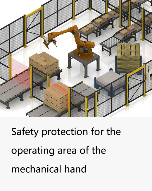
A plant preparing for a humanoid needs an application safety case before installation. Obtain the robot supplier's stopping and stability limits, identify people's access routes and define the safe state for loss of power. That evidence determines whether a conventional guarded-cell arrangement is suitable.
What makes the humanoid case interesting is the one residual risk that a bolted-down arm does not have, and the fact that the standard written for exactly that risk is not finished. So let us start with what is real on the floor right now, then go device by device.
Are humanoids actually doing this work, or is it all demo footage?
Both, which is why the safeguarding question is live rather than hypothetical. A handful of deployments are genuinely industrial, and they are useful reference points — treated here strictly as public news, not as performance claims about anyone's hardware.
- Figure 02 at BMW Spartanburg. Figure AI reports a roughly eleven-month deployment on an active assembly line at BMW Manufacturing in Spartanburg, South Carolina, contributing to production of more than 30,000 X3 vehicles — per Figure, the robots loaded over 90,000 sheet-metal parts across about 1,250 operational hours on weekday shifts (figure.ai).
- Agility Digit at GXO. Agility Robotics' Digit went live at a GXO Logistics facility near Atlanta on 5 June 2024 under the industry's first humanoid Robots-as-a-Service agreement, and in November 2025 Agility announced Digit had moved over 100,000 totes in that live commercial deployment — picking totes on and off AMRs, loading conveyors, stacking containers (agilityrobotics.com).
- BMW Plant Leipzig. BMW Group announced on 27 February 2026 it would deploy humanoid robots in production in Germany for the first time, using the AEON robot from Hexagon, with an initial test in December 2025, further testing from April 2026 and a pilot phase starting in summer 2026 for high-voltage battery assembly (press.bmwgroup.com).
- Tesla Optimus. Tesla has deployed Optimus units inside its own Gigafactory Texas and Fremont plants and, as of early 2026, was scaling production, with a stated long-term ambition of up to roughly 10 million robots a year. A verified count of units actually on production lines was not officially disclosed — treat the large figures circulating on secondary blogs as unverified.
These public deployments establish that industrial trials exist; they do not disclose enough safeguarding detail to copy a cell design or prove that one layout suits every humanoid.
What is ISO 25785-1, and why can't I lean on it yet?
ISO 25785-1 is the first ISO standard aimed squarely at the kind of robot you just bought. Its full title is “Robotics — Safety requirements for dynamically stable industrial mobile robots (legged, wheeled, or other forms of locomotion) — Part 1: Robots.” It is being developed by ISO/TC 299 (Robotics), and it is the first standard written specifically for legged and dynamically-balancing robots — humanoids. It even gives the central concept a name: actively controlled stability, meaning a robot that needs active control to stay balanced and could become unstable if it loses power.
That definition is the whole point of the standard, and the whole reason your cell is different from a normal robot cell. But you cannot certify to it. As of mid-2026, ISO 25785-1 (project 91469) is still a draft — at the Working Draft / Committee Draft stage, with a CD ballot reached during 2026. It is also tightly scoped: it explicitly excludes operator-controlled robots, mechanically guided systems, ride-on devices, exoskeletons, road vehicles, airborne and waterborne systems, floor-cleaning robots, wall-climbing robots, underground use, and non-industrial applications. So it is the right standard for an industrial humanoid, and it is not ready. Track it; do not design your 2026 cell against a draft you cannot buy.
So which published standards do I actually design to?
The same stack as any robot cell with a moving element — you just carry three documents at once instead of one. ISO 10218-1:2025 and ISO 10218-2:2025, published in 2025 as revisions of the 2011 editions, cover the robot and the integrated cell. Those revisions added cybersecurity requirements, robot classification, laser-equipment rules and safety parameterization, and they pulled the former ISO/TS 15066 collaborative-application content directly into the standard, so the biomechanical contact rules now live inside ISO 10218 itself rather than beside it.
Start with ISO 12100 risk assessment and the published robot/application standards where the equipment falls within their scope. ISO 3691-4:2023 covers driverless industrial trucks; it is not a blanket standard for biped locomotion. Identify any truck-like mobile platform separately, then address balance loss and falling hazards with the robot supplier. Use ISO 13855:2024 for applicable safeguard positioning.
Layer one: what does a perimeter laser scanner do here?
A perimeter safety laser scanner is the device that earns its keep on a walking robot. It sweeps a horizontal plane low to the floor and lets you define zones: a larger warning field that slows the cell or raises an alert when someone approaches, and a tighter protective field that commands a safety stop on intrusion. Because a humanoid's working footprint is an area, not a single doorway, this area-based detection is what a flat light-curtain plane cannot give you.
For this personnel-protection task, compare certified safety scanning and industrial LiDAR options by safety role. DAIDISIKE confirms ST27 as Type 3, PL d, SIL 2; verify the exact supplied configuration against the application. The DLD30T-5N perimeter LiDAR is a non-safety perception device. Its range or connection to a safety controller does not qualify it to perform the protective stop.
Layer two: where do the area light curtains go?
The scanner watches the open floor; the light curtains guard the fixed interfaces. Anywhere a person and the robot share a defined opening — a pick-and-place station, a part hand-off, the cell entry point — an access or area safety light curtain creates a detection plane that drops the safety outputs the instant it is broken.
For whole-body and access detection around the larger, less predictable envelope a humanoid cell needs, an area-type unit such as the DAIDISIKE DQSA area safety light curtain covers the walk-up interface where an operator loads or inspects. The choice between a light curtain at a fixed opening and a scanner over an open floor is not a matter of taste — it follows the access routes, and most humanoid cells end up using both. We laid out that plane-versus-area decision in detail in our light curtain vs scanner guide.
How do I set the mounting distance with ISO 13855?
Position safeguards using the applicable ISO 13855:2024 method and the robot's actual hazard envelope. The historical expression S = (K × T) + C below introduces stopping-time and intrusion concepts only; it is not a complete current-edition calculation for a walking humanoid or a scanner field.
- S is the minimum safety distance from the detection plane or zone to the hazard.
- K is the approach-speed constant — 2000 mm/s for a hand/arm approach.
- T is the total stop time of the whole system: device response, controller, and the robot actually coming to rest.
- C is the added distance for detection capability: C = 8 × (d − 14) mm, where d is the curtain's resolution in millimetres, and C is never taken below zero.
The formula above describes a limited perpendicular-approach example, not every scanner or humanoid layout. Under the familiar fine-resolution light-curtain method, the 500 mm floor belongs to the recalculation using K = 1600 mm/s; it is not universal. Resolve reach-over, reach-under, intrusion and field geometry using the applicable ISO 13855:2024 method. Bound total response and stopping time for every robot mode, including payload and stability transitions.
Why isn't a fence enough when the robot can fall over?
Here is the part that makes a legged humanoid genuinely different from a fixed arm or even a wheeled AMR, and it is the reason the area sensors exist. A humanoid can fall or tip if power or balance control is lost, and its centre of mass and reach envelope change as it walks. A bolted arm sweeps a known, repeatable volume. A wheeled AMR stays upright when you cut its power. A biped does neither.
That dynamic, potentially-toppling envelope is exactly the new hazard class ISO 25785-1 was created to address, and it is precisely what a static fence does not fully cover. So the fence handles the gross boundary, the interlocked and guard-locked access door handles entry, and then the perimeter scanner and area curtains handle the part the fence cannot: a person in the floor zone the robot might step or fall into, and the interfaces where people and the machine meet on purpose. Layered, not single-device — because no one layer covers every way a person can reach this particular hazard.
And no, the robot's own LiDAR is not your safety device
Do not infer safety capability from onboard cameras or LiDAR. Ordinary navigation and perception sensors must not be credited with a protective stop. A documented onboard safety device can be considered only with validated coverage, response and integration for the actual function; external scanners likewise require application validation. Sensors do not contain a falling robot. The mobile-robot standards explainer discusses the separate perception and protection roles.
What does the finished shopping list look like?
Pulling it together, the safeguarding bill of materials for a typical 2026 humanoid workcell reads almost exactly like a conventional robot cell — which is the reassuring part:
- A physical fence with one or two access points, each with a coded, guard-locking interlock so the door cannot open while the robot moves and the cell cannot run while the door is open.
- One or more perimeter safety laser scanners covering the swept floor zone, with warning and protective fields, and field sets switched by the cell's operating mode.
- Area / access safety light curtains at every fixed human interface and the cell entry, resolution chosen by what they must detect, and each mounted at its ISO 13855 distance.
- The robot's own perception layered on top as behaviour, never counted in the safety function's PL or SIL.
For the wider picture on where the standards genuinely sit versus where the marketing runs ahead of them, our companion piece on humanoid robot safety standards in 2026 factories goes deeper on what is still unsolved.
References & standards cited
- ISO 25785-1 (under development) — safety requirements for dynamically stable industrial mobile robots (legged); ISO/TC 299, project 91469, still a draft.
- ISO 10218-1:2025 — industrial robots; 2025 revision, ISO/TS 15066 content absorbed.
- ISO 13855 — current positioning scope and method; the simplified expression in this article is historical.
- Figure AI — production at BMW — public reference for the Spartanburg deployment.
- Agility Robotics — Digit moves over 100k totes — public reference for the GXO deployment.