
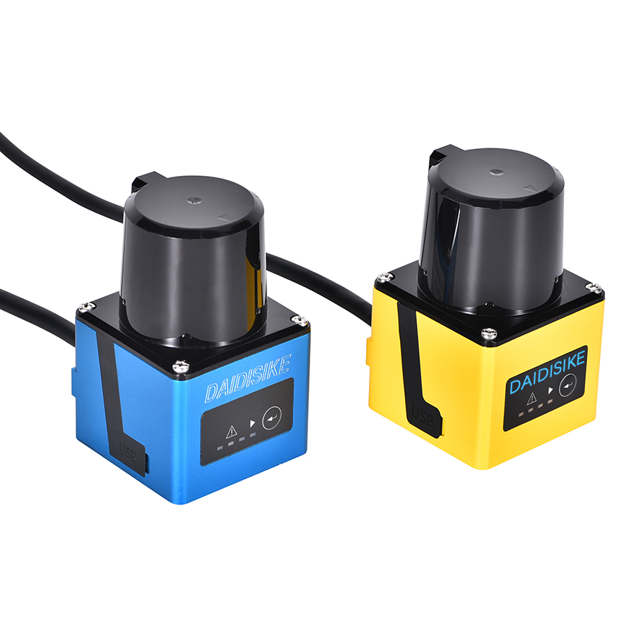
Direct answer: ANSI/A3 R15.08 is a three-part voluntary American consensus standard for industrial mobile robots. Part 1 addresses the IMR, Part 2 the integrated system and application, and Part 3 its use. It does not replace a site-specific risk assessment. Any personnel-protection function must be designed and validated as a complete safety function; navigation or obstacle-avoidance LiDAR alone is not a certified protective device.
Industrial mobile robots increasingly share industrial spaces with people, racks, conveyors and fixed machinery. Their hazards move with the machine and change with the application and current operating environment. R15.08 therefore matters to the robot maker, the party integrating the system or application, and the user who manages it throughout operation.
The current public A3 catalogue lists Part 1 as ANSI/RIA R15.08-1-2020 (reaffirmed in 2026 with no technical change), Part 2 as ANSI/A3 R15.08-2-2023, and Part 3 as ANSI/A3 R15.08-3-2026, published on April 23, 2026. This guide explains the public scope of those editions and the device boundary that matters when a mobile-robot application combines safety scanning with navigation or ordinary obstacle detection.
What R15.08 actually is, and who publishes it
R15.08 is an American National Standard developed by the Association for Advancing Automation (A3) — the trade body that absorbed the Robotic Industries Association (RIA) and is now the secretariat for the R15 robot-safety committee. You will see the older “ANSI/RIA R15.08” prefix on Part 1 and the newer “ANSI/A3 R15.08” prefix on later parts; the rename is administrative, not technical.
A3’s public overview classifies IMRs by configuration. Type A is an autonomous mobile platform; Type B adds a passive or active attachment other than a manipulator; Type C combines a mobile platform with an industrial manipulator. Those definitions are more reliable for scope decisions than using AGV and AMR as loose marketing labels.
Scope decisions can be technical and jurisdiction-specific. Confirm the exact machine configuration, attachments, intended use and current editions before quoting a clause or claiming conformity. Where a machine may also fall within another product standard, document which requirements apply and how conflicts or gaps are resolved in the project risk assessment.
Part 1 — Requirements for the Industrial Mobile Robot (the manufacturer)
ANSI/RIA R15.08-1-2020, reaffirmed as R2026, addresses requirements for the individual Industrial Mobile Robot. A3 states that the reaffirmation has no technical differences from the 2020 text. At a project level, Part 1 should be read as the IMR-design layer, not as proof that a deployed application is safe.
- Hazard identification and risk assessment: identify the safety functions needed for the intended IMR and justify their required performance.
- Safety by design: implement appropriate risk-reduction measures and safety-related controls for the IMR configuration.
- Verification and validation: show that the implemented measures meet their specifications; component ratings alone do not validate the complete function.
- Information for use: give downstream integrators and users the limits, assumptions and instructions needed to keep the IMR within its intended operating conditions.
Part 1 information is an input to the application risk assessment. The integrator and user must still evaluate the installed system, interactions, current operating environment and reasonably foreseeable changes. No individual certificate or sensor model demonstrates the safety of the complete application.
Part 2 — Requirements for IMR systems and applications (the integrator)
ANSI/A3 R15.08-2-2023 is the part most plant engineers underestimate. It addresses what happens when one or more IMRs are integrated into an actual site: the layout, the fleet manager, the interactions with people and with other equipment, and the configuration of safety functions to the real environment.
Public ANSI and A3 descriptions establish the Part 2 scope but do not expose every normative clause. The following are therefore practical review topics, not quoted clause requirements:
- Application risk assessment. Reassess the installed application, including traffic, aisle geometry, payloads, docking and interaction with people or other machinery.
- Safeguard configuration. Configure fields, modes and interfaces from measured stopping performance and the actual environment, not a generic template.
- System interactions. Consider fleet behaviour, communication loss, shared spaces and interfaces with fixed stations.
- Complete-function validation. Test and document the sensor, logic, output devices, stopping elements and foreseeable operating conditions before acceptance.
The practical lesson is simple: conformance evidence for the IMR is necessary input, not application acceptance. The installed system must be assessed and validated against its real layout, traffic, payload, speed, stopping behaviour and interfaces.
Part 3 — Requirements for the User (lifetime operation)
ANSI/A3 R15.08-3-2026 was published on April 23, 2026. A3 describes it as guidance for users to maintain acceptable risk in workplaces operating IMR applications. Its public summary emphasizes safe use, risk assessment, management of change in both the application and the current operating environment, and lifecycle personnel safety.
For implementation, maintain a documented process for training, inspection, incident learning and change review. When layout, payload, speed, traffic, software, attachments or interfaces change, determine which hazards and safety functions are affected and revalidate those functions before relying on the changed system.
The operational record should connect each change to the risk assessment, verification evidence, validation result and responsible person. A calendar inspection by itself is not enough when a change has altered the assumptions behind a safety function.
R15.08 and ISO 3691-4 side by side
These documents overlap in mobile-machine safety, but their public scopes and structures are not identical. Use the comparison as a scope check only; the purchased standards and the project’s regulatory assessment control the design.
| Topic | ANSI/RIA & A3 R15.08 | ISO 3691-4:2023 |
|---|---|---|
| Publisher | A3 develops the text; ANSI approves the American National Standard | ISO/TC 110/SC 2 |
| Published scope | Industrial mobile robots, IMR systems and IMR applications | Driverless industrial trucks and their systems |
| Examples named publicly | Type A platform, Type B with non-manipulator attachment, Type C with manipulator | AGV, AMR, bots, automated guided carts and other driverless industrial trucks |
| Structure | Part 1: IMR; Part 2: system/application; Part 3: use | One product/system standard with operating-zone considerations in Annex A |
| Current editions checked | R15.08-1-2020 (R2026), R15.08-2-2023, R15.08-3-2026 | ISO 3691-4:2023; a revision project is under development |
| How to apply | Confirm classification, applicable parts, risk assessment and complete-function validation | Confirm the truck/system is in scope and apply its safety requirements and verification |
| Legal or contract status | Consensus standard; separate OSHA, state, local and contract duties still apply | International standard; regulatory use depends on the relevant jurisdiction and conformity route |
A machine may need assessment against more than one document, but “designed to both” is not a substitute for a recorded scope decision. Start with the machine definition and intended use, then document the applicable editions and validate every claimed safety function under the installed conditions.
What R15.08 means for safety LiDAR scanner selection
Do not select a device from the word “LiDAR” alone. Compare the documented industrial LiDAR scanner and safety-scanner classes before assigning any safety function. IEC 61496-3:2025 covers AOPDDR protective equipment designed to detect people, but it does not prescribe the detection-zone dimensions or define the hazardous state for a particular application. The risk assessment and complete safety-function design must supply those answers.
For DAIDISIKE products, keep the boundary explicit:
- Certified personnel protection: the ST27 safety laser scanner is the confirmed Type 3, PL d, SIL 2 model. Those ratings belong to ST27 and do not transfer to another scanner or to the complete application.
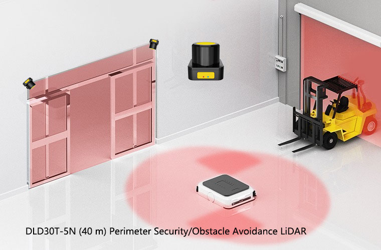
- Navigation and ordinary obstacle detection: DLD, SDLD, DLDS and JPTG products are perception devices for mapping, measurement, navigation or non-safety obstacle awareness. They must not replace ST27 in a personnel-protection safety function.
- Protective-field design: derive the field from measured stopping performance, response times, tolerances, approach conditions, mounting and the current operating environment. Validate every relevant mode and field transition.
- Complete stop chain: verify the scanner, safety logic, OSSD wiring, output devices, brakes or drive control, reset behaviour and fault response together. A component certificate is not application validation.
Common mistakes to check on R15.08 projects
Treating Part 1 conformance as the whole answer. A vendor states the IMR is R15.08-1 compliant, and the buyer assumes that this also validates the deployment. The installed system still needs an application assessment, integration evidence and acceptance checks under the applicable requirements.
Mixing up navigation LiDAR and safety LiDAR in the BOM. A line item that says “LiDAR sensor” can hide either kind. Substituting a navigation unit can invalidate a personnel-protection design. Specify the part number, intended safety function and documented IEC 61496-3 Type where relevant.
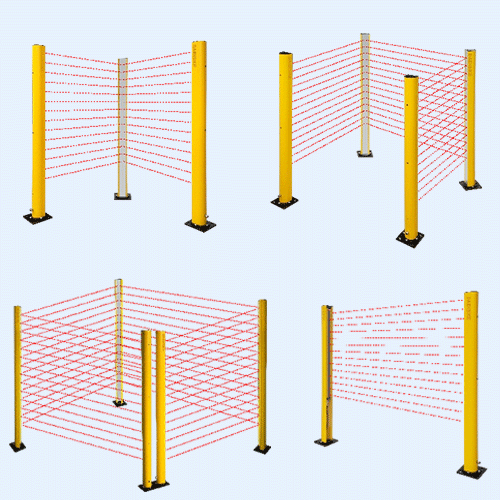
Forgetting the fixed-station side of the deployment. AMRs dock into pick stations, conveyor takeaways, and charging banks. Those stations create pinch and crush hazards that have nothing to do with the vehicle’s own safety scanner. We cover this in the companion article on AGV and AMR safety laser scanners; the short version is that fixed-station guarding (light curtains, area scanners, interlocks) and on-vehicle safeguarding must be designed as one system.
Skipping the change-management discipline. A layout is reorganised; a new SKU arrives that changes pallet height; a third shift increases pedestrian traffic. Review these changes against the risk assessment and revalidate the affected safety functions where their assumptions or performance have changed. Keep the decision and supporting evidence in the application record.
Where DAIDISIKE fits — honestly
DAIDISIKE offers two distinct device classes for mobile-robot projects. ST27 is the Type 3, PL d, SIL 2 safety laser scanner for suitable personnel-protection functions. The DLD05A3 (5 m) and DLD20A5 (20 m) support ordinary obstacle detection; DLD30T-5N and SDLD-05A also serve non-safety perception roles. These devices do not inherit ST27’s safety ratings. At fixed stations, assess the appropriate light curtain, interlock or other safeguard together with the docking and material-transfer hazards. The chosen device and control interface must match the validated safety function.
What we will not tell you is that buying a particular scanner model makes a deployment R15.08 compliant. Compliance is a system property, not a part number. Where we can usefully help is on the device-selection conversation — range, field sets, mounting, interface to the safety controller — inside the broader design your integrator owns.
The bottom line
All three R15.08 parts are now published. Use their separate design, integration and use scopes to document responsibilities across the project. If you are specifying an IMR fleet, ask the vendor for Part 1 evidence, agree Part 2 application deliverables with the integrator, and establish the Part 3 operating and change-management process. Record the applicable editions and legal or contractual requirements. Scanner selection, field configuration and fixed-station guarding then become traceable parts of the complete safety assessment.