
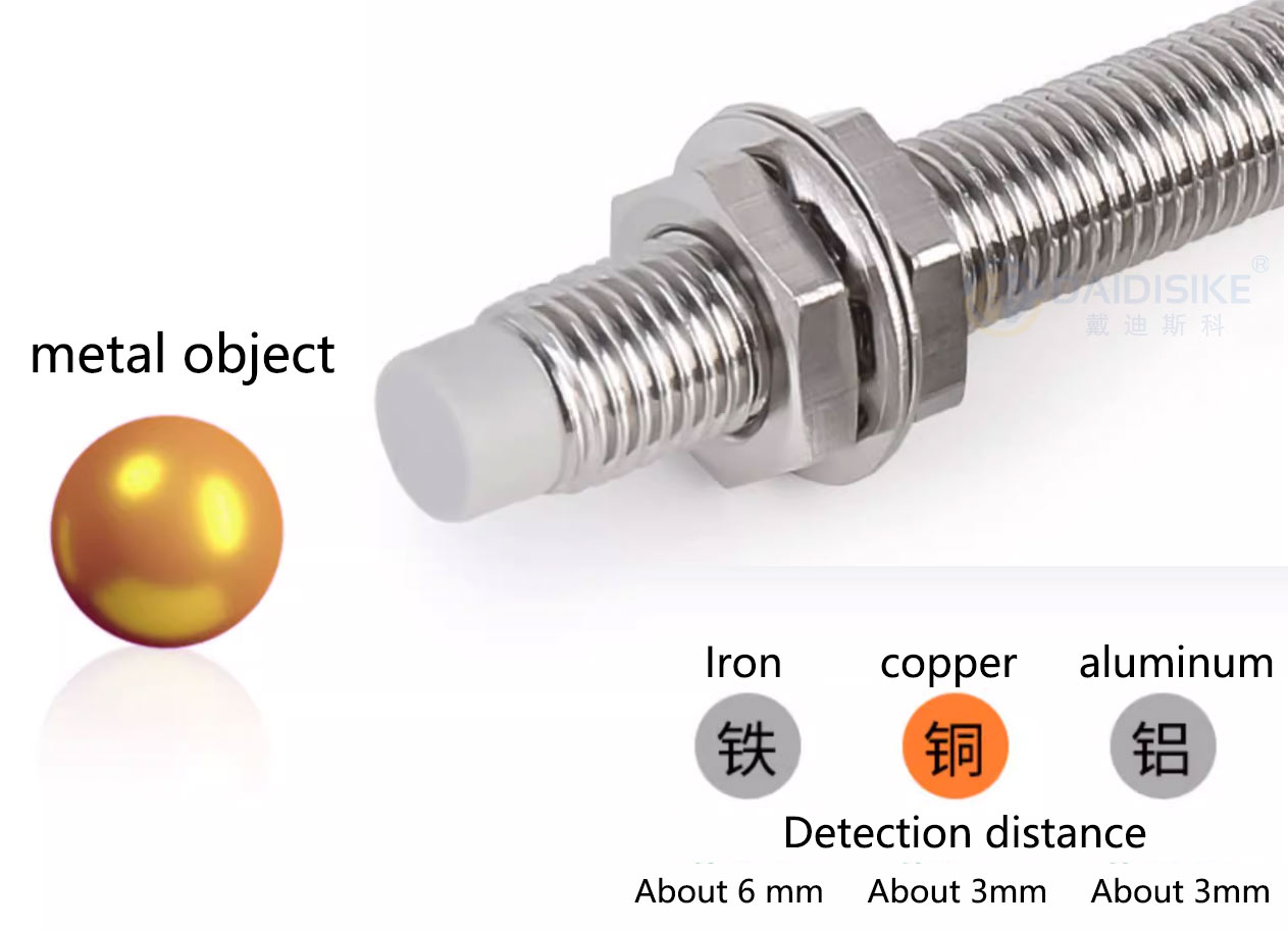
Every inductive proximity switch you have ever specified came with a hidden assumption: the target is mild steel. The published sensing distance — the rated operating distance, Sn — is measured against a standard mild-steel target. That is the reference that defines a reduction factor of 1. Detect anything other than mild steel and the sensor reads it at a shorter distance, and you are supposed to know to multiply.
Most engineers half-remember this and then forget it on the bench, which is how you end up with a part-present sensor that works on the steel prototype and intermittently misses on the production aluminium part. So let us be precise about the numbers, then explain why factor-1 sensors make the whole correction table disappear.
What is the reduction factor on a standard sensor?
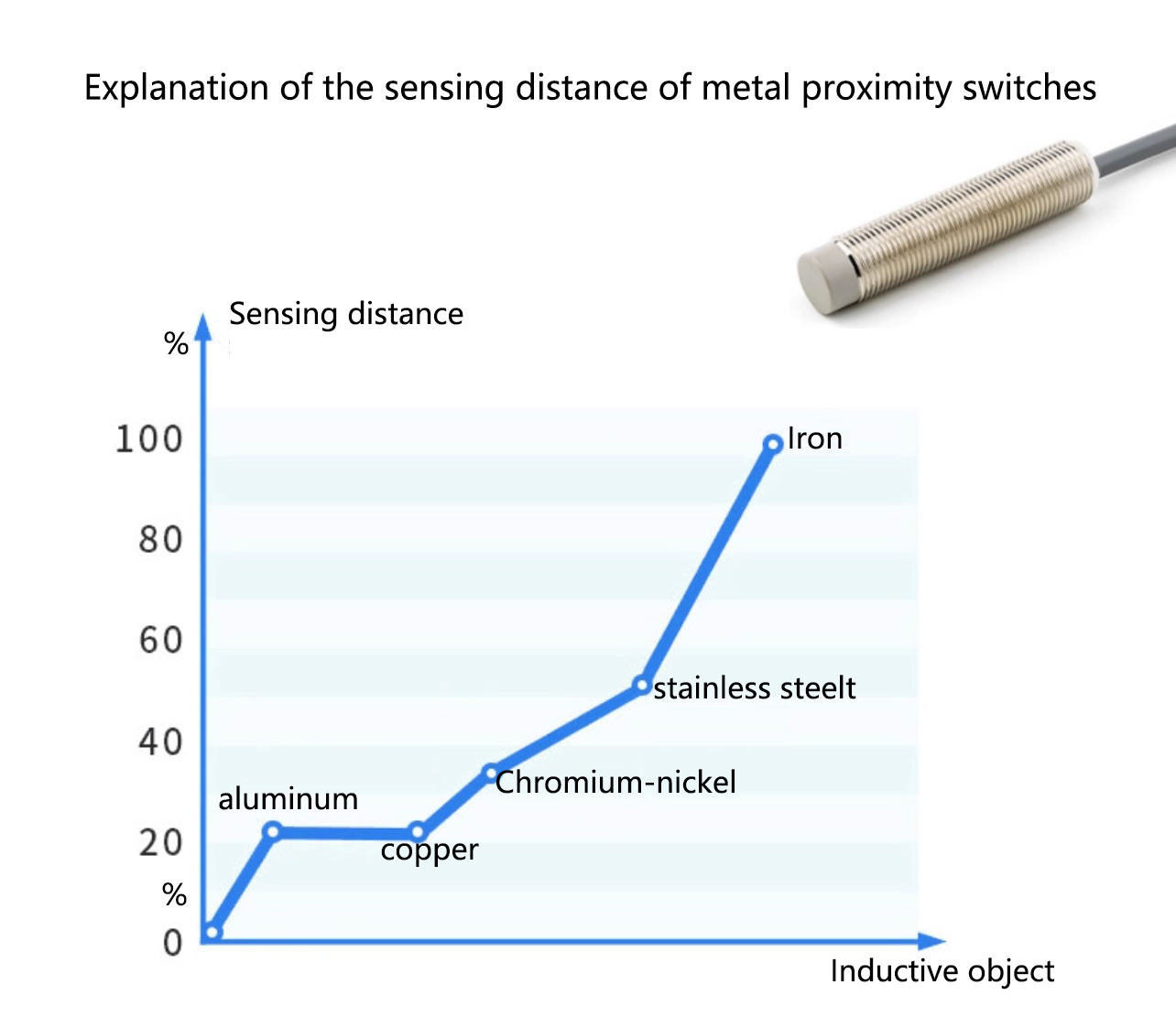
The reduction factor (k-factor) is the multiplier you apply to the rated sensing distance for a given target metal. Mild steel is the reference at 1.0; everything non-ferrous and even stainless reads short. Typical published figures for a standard ferrite-core inductive sensor look like this:
| Target metal | Approx. reduction factor | Effect on rated distance |
|---|---|---|
| Mild steel (reference) | 1.0 | Full rated Sn |
| Stainless steel (304 / V2A) | ~0.8 | ~80% of Sn |
| Brass | ~0.5 | ~half |
| Aluminium | ~0.4–0.5 | ~half |
| Copper | ~0.3 | ~one third |
Read the aluminium row again, because it is the one that bites. On a standard sensor an aluminium target is sensed at only about half the distance of a mild-steel target, per AutomationDirect's technical library. If your fixture gives you a 4 mm gap and you chose an M12 with a 4 mm rated range on steel, that same sensor effectively has a ~2 mm range on aluminium — and your part now sits outside the detection window. The fix on a standard sensor is to step up to a larger barrel or close the gap. Both cost you mounting freedom.
How does a factor 1 sensor detect every metal the same?
Factor 1 means the reduction factor is 1 for every metal — steel, stainless, aluminium, brass, copper all sensed at the same rated distance. The trick is in the coil. A conventional inductive sensor has a single coil wound on a ferrite core, and that core is exactly what makes the response metal-dependent: it couples strongly to ferrous targets and weakly to non-ferrous ones.
One implementation replaces the ferrite core with separate transmit and receive coils. This is the construction behind designs such as Turck's uprox family. With no ferrite to bias the result toward steel, the detection becomes near-uniform across metals. Turck's uprox3 line, for example, publishes flush-mountable all-metal switching distances of roughly 3 mm at M8, 6 mm at M12, 10 mm at M18 and 20 mm at M30 — the same number whether the target is steel or aluminium. Contrinex Series 600 and Series 700 are likewise true factor-1 sensors that sense steel and aluminium equally with no reduction in distance.
Why is a factor 1 sensor also weld-immune?
The Turck uprox3 description associates its coil design with magnetic-field immunity. That is evidence for that product family. Factor 1 alone does not specify an immunity test level, cable protection or spatter resistance. Confirm each requirement on the selected sensor.
The numbers explain why this matters in a weld cell. Contrinex states that 50 Hz AC welding equipment can produce magnetic field strengths reaching about 40 mT, and their 2021 S600 application example describes medium-frequency resistance welding at around 15 kA. Welding current alone does not specify the field at a sensor; conductor geometry, distance and frequency matter. Use the exact sensor’s immunity specification, not this application current as a universal rating.
When do aluminium and EV battery welding justify factor 1?
Because both problems show up in the same cell at the same time. Automotive body-in-white and EV battery assembly increasingly join aluminium and mixed steel/aluminium structures — battery trays, enclosures, panels. That hands you two requirements simultaneously.
First, the metal is non-ferrous, so a standard sensor reads it at roughly half range and detection turns flaky. Second, MF resistance welding of aluminium assemblies needs welding currents about two to three times higher than for steel of equivalent thickness, because aluminium has lower electrical resistance — which means an even stronger weld field around the sensor. Where the gap and field exposure require it, specify both factor-1 detection and separately verified weld-field immunity. That is not a coincidence; it is why the two features ship together in this market, and why these cells are the primary application driver for factor-1 weld-immune sensors. If you are guarding or sensing in this kind of line, our EV battery machine-safety guide covers the wider cell layout.
What housings and ranges do weld-immune sensors use?
A weld cell is mechanically violent as well as electromagnetically noisy — spatter, abrasion, and the occasional fixture collision — so weld-immune sensors are built tougher than a general-purpose prox. Contrinex Series 700 “Full Inox” sensors use a one-piece sealed V2A / AISI 303 stainless-steel housing for mechanical, abrasion and chemical resistance, with an optional ACTIVSTONE ceramic coating that adds weld-spatter resistance.
Range matters too, and for an unexpected reason: the further the sensor face sits from the fixture, the less often a misplaced part or a moving tool smashes into it. So several weld-immune factor-1 lines offer extended sensing ranges — up to around 16 mm on some Series 700 models — specifically to reduce collision and crash damage. An M8 S600, by contrast, gives up to about 2 mm, with the broader line reaching up to ~8 mm. Pick the range that buys you clearance, not just the one that reaches the target.
When is a standard sensor still the right answer?
Do not reflexively put factor-1 on everything. This is an opinion I will defend: over-specifying weld-immune sensors on a clean line is just money handed to the catalogue. If your target is a fixed mild-steel cam, flag or bracket, in a cell with no weld field, a standard inductive sensor is cheaper and exactly correct — the reduction factor on steel is 1.0 anyway, so you gain nothing.
Factor-1 earns its premium in three situations, and you should be able to name which one applies before you order:
- The target metal varies. Mixed steel and aluminium parts on the same fixture, where a single de-rating factor cannot cover both.
- The target is non-ferrous. Aluminium, brass or copper, where a standard sensor loses 50–70% of its range.
- There is a weld field nearby. Resistance or MF welding: assess magnetic immunity separately; Factor 1 alone is not an immunity rating.
For the DAIDISIKE M3–M30 catalogue, the same sizing discipline applies as for any inductive switch: size the housing to the target gap first. Our M12 and M18 / M30 three-wire families cover the longer-range fixture work, while the M8 fits the tight tooling. The full selection and wiring logic — including how reduction factor interacts with sensing distance — is in our proximity-switch selection guide.
The short version for a buyer in 2026
Specify Factor 1 when metal-dependent range would otherwise prevent reliable detection at the required gap. Specify weld-field immunity when the electromagnetic environment requires it, and verify the housing and cable against heat, spatter and cleaning exposure. Use theDAIDISIKE proximity switch catalogue for standard process sensors; it does not establish Factor 1 or weld-immune capability for those models. Ordinary process sensors are not personnel-protection devices.
Related reading
DAIDISIKE M12 Metal Inductive Proximity Switch
The workhorse fixture size — three-wire DC, PNP/NPN, NO/NC variants.
EV Battery Manufacturing — Machine Safety
Cell-level guarding for the aluminium and mixed-metal assembly lines factor-1 sensors serve.
Ultimate Guide to Proximity Switches
Selection, wiring and troubleshooting, including reduction factor and sensing distance.