
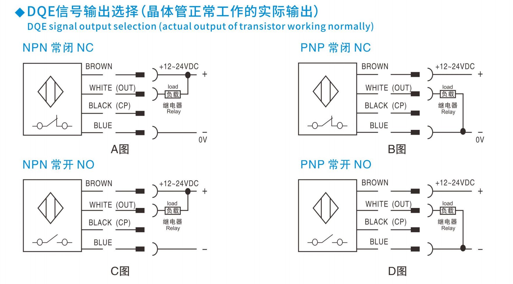
Specifying a safety laser scanner is the easy part. The interesting work starts when the box arrives and someone has to decide exactly where on the chassis it goes, at what height, at what angle, on what bracket, with the cable routed which way. Every one of those choices shifts what the scanner can see, what counts as a stopping distance, and whether the installation will pass a safety audit. This is the side of LiDAR integration that rarely appears on a datasheet.
Mounting height — ankle detection vs perimeter
There are two distinct mounting regimes, and they should not be mixed up.
Area protection on an AGV / AMR
On a driverless industrial truck under ISO 3691-4, the scanner is doing area protection — it watches a 2D plane across the floor in front of the vehicle to catch ankles and legs before the truck can hit them. Field practice, consistent with ISO 3691-4 personnel-detection requirements, puts the scan plane somewhere in the 150–200 mm band above the floor on the leading edge of the chassis. Lower than about 100 mm and the beam catches floor texture, cable covers and drain grates; higher than about 300 mm and an adult can either step over the field or crawl beneath it.
Height and rated detection capability must be assessed together against the application and exact manual. There is no universal rule requiring 50 mm resolution below 300 mm. ST27, for example, has a published 70 mm detection capability; do not invent a configurable 50 mm setting. Check under-reaching, stepping over, vehicle geometry and detection tests rather than copying a generic height rule.
Fixed perimeter / area guarding
For a stationary perimeter or a robot cell footprint, the scan plane sits where the hazard requires — sometimes at ankle height to catch an approach from the floor, sometimes at chest or body height where the device is monitoring a fence line or a vehicle lane and a horizontal ‘tripwire’ geometry is appropriate. In a long-range perimeter role, the scanner often looks horizontally across a yard or a building face. The governing question is the same: where does a person realistically enter the protected area, and does the configured field intersect every one of those paths.
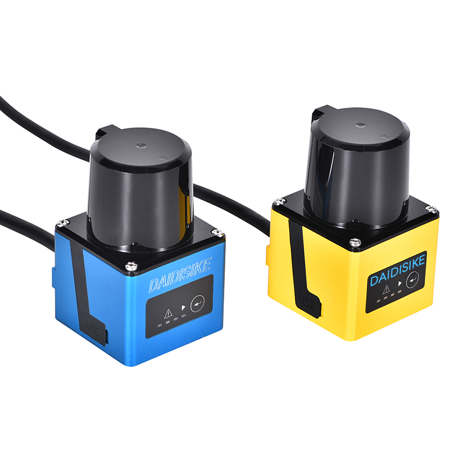
Tilt angle — the geometry that bites
A safety laser scanner is built around a flat, horizontal scan plane. The instant the housing pitches forward or back, that plane projects to a sloped line on the floor, and the geometry changes faster than people expect.
The arithmetic is straightforward. For a small tilt angle θ, the beam at a horizontal range R drops below the mounting plane by approximately R × tan(θ). That gives the working numbers:
| Downward tilt | Drop at 2 m | Drop at 4 m | Drop at 10 m |
|---|---|---|---|
| 1° | ~35 mm | ~70 mm | ~175 mm |
| 2° | ~70 mm | ~140 mm | ~350 mm |
| 5° | ~175 mm | ~350 mm | ~875 mm |
At 180 mm mounting height and 5 m horizontal range, a 2° downward pitch lowers the center ray by about 175 mm, leaving only about 5 mm nominal clearance on a level floor. Floor variation can then intersect the beam. An upward tilt can raise the far scan plane above the intended target height.
Use the orientation permitted by the model manual and verify it through the full range and motion envelope. A generic allowance of 0–5° is not safe mounting guidance: the table shows how quickly clearance changes. After any tilt or height change, repeat detection and stopping checks, including ramps, pitch, roll and load effects.
The behind-scanner dead zone
A rotating safety scanner sweeps a sector — commonly 270 degrees — not a full circle. The remaining arc, behind the housing, is unscanned: it is where the connectors, the electronics and the mounting interface live. That rear dead zone is non-negotiable; it cannot be configured out.
There is also a small near-field dead zone — typically on the order of tens of millimetres directly in front of the optics — where returns are too fast for the electronics to time. Standards (ISO 13855 supplementary guidance, and IEC 61496-3 product testing) require that the unprotected space between the configured protective zone and any adjacent physical structure be smaller than the minimum detectable object, so that a person cannot squeeze in between.
Mounting implications:
- Point the rear dead-zone arc into the vehicle body, a wall, or a continuous physical guard — never into floor a person can stand on.
- Where the scanner sits at the leading corner of an AGV, accept that the side furthest from the vehicle has a sensor-to-edge blind sliver. Either close that gap with bumper guarding, a mechanical safety bumper, or a second scanner.
- Keep the near-field clear — no part of the bracket or chassis must protrude into the first few centimetres in front of the lens, or it will appear as a permanent intrusion and force the OSSD outputs off.
Multi-scanner installations
On a long AGV that drives in both directions, on a tugger with a trailer, or on a perimeter with a corner that one device cannot see around, a single scanner is not enough. Two or four scanners become the answer — but they bring their own geometry problems.
Three rules apply.
- Avoid mutual blinding. Two scanners on the same horizontal plane pointed toward each other will see each other's emitted pulses and can mutually trip. Offset them vertically by a few centimetres, angle them slightly, or use devices with built-in interference suppression.
- Stitch fields, do not overlap them carelessly. Provide sufficient overlap to account for tolerances and shadows. Field shapes are software regions, not emitted barriers; overlap itself does not cause a trip. Address optical interference using manufacturer guidance without creating a coverage gap.
- Switch field sets in sync. If field sets change with vehicle speed or cell state, every scanner has to switch together, driven from the same safety controller. A mismatch — one device on the high-speed field, another still on the low-speed field — is a latent unsafe condition.
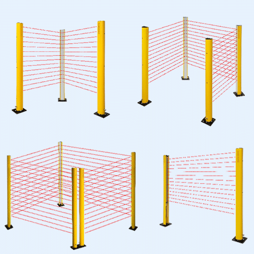
Bracket design — rigid, isolated, stable
A safety laser scanner does not need a heavy bracket, but it does need a stiff one. The whole field configuration is referenced to the scanner’s own coordinate frame; if the bracket flexes a degree under vehicle vibration, the protective field swings by that degree, and at 5 m that is about 90 mm of error.
What works in practice:
- Machined aluminium or thick folded steel, bolted with at least two captive fasteners to a planar reference face on the chassis. Avoid single-bolt mounts — they pivot.
- Vibration isolation only where the chassis transmits genuinely heavy shock — IEC 61496-3 requires scanners to pass vibration and shock immunity tests (IEC 60068-2-64 broadband random, IEC 60068-2-27 shock), but extended operation at the edge of those limits stresses internals. Soft mounts must not introduce sub-degree drift under cornering loads.
- Thermal stability — bracket material should not expand or twist over the equipment’s operating temperature range, especially in outdoor perimeter installations.
- Adjustability with lockable settings — slotted holes are fine for initial alignment, but the final position has to be locked with witness marks or a positive stop so a vibration-loosened bolt cannot rotate the device without anyone noticing.
Cable routing
OSSD cables are safety circuits. They deserve the same discipline as any other safety wiring.
- Use the shielded cable specified by the scanner manufacturer and terminate shielding according to the exact EMC instructions and site bonding design. A floating shield invites the kind of noise pickup that produces intermittent OSSD trips.
- Route the OSSD cable physically separated from drive-motor and variable-frequency-drive cables. A parallel run inside the same conduit is a classic source of nuisance stops on AGVs.
- Provide strain relief at the scanner connector and a service loop so the connector is not loaded in tension. On mobile platforms, run the cable through a flexible chain or sleeve rated for the bend cycle count of the vehicle’s life.
- Keep cabling inspectable. A pinched OSSD line inside a sealed chassis cavity is a real and recurring cause of mid-life safety incidents.
Sun, light and reflective surfaces
A safety scanner is an active emitter, but its receiver still has to discriminate its own modulated returns against ambient light. Three orientation rules pay back in fewer nuisance trips:
- Avoid pointing the receiver directly at low-angle sun — an outdoor perimeter scanner facing due east or west at sunrise or sunset is asking for trouble.
- Watch for highly retro-reflective surfaces in the field of view — mirror-finished stainless, certain reflective safety tapes, or glass at oblique angles. They can produce unexpectedly long returns.
- On wet outdoor floors, a low scan plane can pick up specular reflections of overhead lighting. A few centimetres of mounting height and a small downward tilt often solves it.
Floor visibility — the practical compromise
The scan plane has to be low enough that a person’s ankle is intercepted, and high enough that ordinary floor variation does not constantly trip the device. On a polished concrete floor with no expansion joints, 150 mm is comfortable. On a warehouse floor with tile joints, drainage grates, cable covers and the occasional ramp, 180–200 mm with a level mounting tends to behave better. On grating or open mesh — a real issue in food and chemical plants — the scanner may need to be raised and the resolution lowered, with mechanical guarding added beneath the field to prevent under-crawl.
Integration into the safety logic chain
A safety laser scanner does not stop a machine on its own. Its dual OSSD outputs feed a safety controller (or, on smaller systems, a safety relay), which in turn drives the contactors, drive enables and brakes that actually remove energy from the hazard. The whole chain — sensor, logic, actuator — is what carries the Performance Level under ISO 13849-1 or the SIL under IEC 62061.
The integration points the mounting engineer should check alongside the safety integrator:
- Response time budget. The scanner’s own response time (a multiple of its scan period, depending on the configured multiple-sampling) plus the safety controller’s processing time, final-element delay and complete machine stopping time have to fit inside the ISO 13855 safety distance calculation. Increasing the multiple-sampling count to suppress nuisance trips extends response time — the protective field must grow to match.
- Field-set switching. Speed-dependent or state-dependent field sets must be commanded by safety-rated signals, not by an ordinary PLC output. The switch itself is a safety function.
- Reset behaviour. After an OSSD trip, the restart behavior must follow the application risk assessment and approved design. Where manual reset is required, it must not initiate hazardous motion by itself; validate visibility, occupancy and start conditions.
- Diagnostics. Wire the scanner’s diagnostic and warning outputs into the supervisory PLC. They are not safety signals, but they catch lens contamination and alignment drift before they become OSSD trips.
AGV mounting vs fixed perimeter mounting at a glance
| Parameter | AGV / AMR area protection | Fixed perimeter / cell |
|---|---|---|
| Typical scan-plane height | 150–200 mm above floor | Application-dependent; ankle, knee or chest level |
| Tilt angle | Model-approved orientation, validated over the full field | Level, or matched to a sloped surface |
| Detection capability | Exact rated detection capability and application-specific height limits | Sized to the smallest body part that can enter the field |
| Bracket priority | Rigid, vibration-tolerant, lockable alignment | Rigid, thermally stable, anti-tamper |
| Cable concern | Flex life through chain, separation from drives | Conduit, weather sealing, EMC distance |
| Governing standard | ISO 3691-4, ISO 13855, IEC 61496-3 | ISO 13855, ISO 13849-1, IEC 61496-3 |
Common mounting mistakes
- Mounting height and detection capability selected from a generic rule instead of the exact scanner manual and application tests.
- Forward tilt of two or three degrees on an AGV — the protective field reaches into the floor at maximum range and the vehicle trips on every expansion joint.
- Rear dead-zone arc pointed into a working aisle instead of into the chassis. A person walking up from behind is invisible to the device.
- OSSD cable run alongside the drive-motor cable, no shield termination. Random nuisance stops that the maintenance team cannot reproduce.
- Single-bolt mount or a flimsy sheet-metal bracket that flexes under cornering. Field geometry drifts and no one notices until validation fails six months later.
- Field sets sized in CAD but never validated on the floor with a physical test piece. The drawing matches the configuration file; neither matches reality.
Validation — walk the zone
A scanner installation is signed off the way a light-curtain installation is signed off — by physically testing it. Take a calibrated test cylinder sized to the scanner’s stated detection capability (typically 50 mm or 70 mm dark diffuse target) and walk it slowly around the boundary of every protective and warning field set the device will use in service. Confirm the OSSDs drop within the documented response time at every approach direction. For an AGV, repeat the test at every speed-dependent field set. Photograph or video the test, record the date, the engineer, the firmware version and the configuration revision. Under ISO 3691-4 and ANSI/RIA R15.08, this evidence belongs in the safety file.
DAIDISIKE DLD scanner mounting notes
Use the LiDAR model categories and mounting requirements to confirm whether the device is a safety scanner or non-safety perception LiDAR. ST27 is confirmed as Type 3 / PL d / SIL 2. DLD/SDLD mounting examples below concern sensing only and do not create certified protective fields. See the field-switching validation guide when mounting interacts with speed or direction changes.
- DLD05A3 (5 m): compact AGV obstacle avoidance — mounted on the leading edge of the chassis, scan plane at 150–200 mm, level orientation.
- SDLD-05A (14 m TOF): non-safety object monitoring where the documented sensing range and environment fit.
- DLD20A5 (20 m): non-safety AMR sensing and larger-area monitoring — tilt and height as for DLD05A3, but with extra attention to floor variation at the longer field distance.
- DLD30T-5N: non-safety measurement range is 30 m at 90% remission and 10 m at 10% remission. Fixed perimeter and outdoor non-safety area monitoring — bracketed onto a wall, post or fence column, with weather-rated cabling and a clear line of sight to the protected zone.
Related reading
Industrial Safety LiDAR — Complete Reference
The full engineer's reference for industrial safety LiDAR — physics, standards and selection.
DAIDISIKE DLD05A3 / DLD20A5
5 m and 20 m obstacle-avoidance scanners for AGV and AMR mounting.
AGV & AMR Safety Laser Scanners
How safety scanners protect mobile robots in warehouses and factories.
References
- ISO 3691-4:2023 — Industrial trucks. Safety requirements and verification. Part 4: Driverless industrial trucks and their systems.
- ISO 13855 — Safety of machinery. Positioning of safeguards with respect to the approach speeds of parts of the human body.
- IEC 61496-1 / IEC 61496-3:2025 — Safety of machinery. Electro-sensitive protective equipment, including AOPDDR (safety laser scanners) and the associated environmental immunity tests.
- ANSI/RIA R15.08 — Industrial mobile robots, safety requirements (North American practice).
- ISO 13849-1 / IEC 62061 — Functional safety of machinery control systems (Performance Level / SIL).