Machine enclosure doors
Monitor an opening guard on a machine enclosure. Check the mounting gap, alignment and controller interface for the actual door arrangement.

DAIDISIKE · GUARD DOOR MONITORING
A dedicated model reference for selection, technical enquiries and bid documentation.
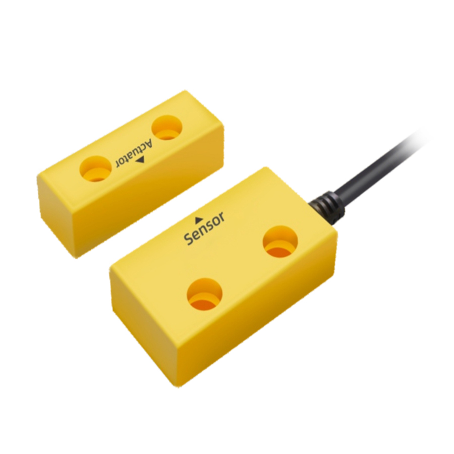
DX-R1 family reference — sensor and actuator pair
The DX-R1-B is a non-contact coded switch for monitoring movable machine guards. Its sensor and matching actuator provide guard-status signals without a mechanical contact between the two parts.
Use this page to identify the DX-R1-B in your project. The technical reference below is based on our DX-R1 family; the quotation identifies the output, actuator coding and connection supplied for your order.
Model reference: DX-R1-B · Manufacturer: DAIDISIKE
Published values from the DX-R1 English manual are provided for initial selection. Confirm the applicable values and drawing for the complete DX-R1-B configuration offered for your project.
| Parameter | Family reference value |
|---|---|
| Operating voltage | 24 V DC ±15% |
| Operating current | 30 mA |
| Output current | 150 mA |
| Response time | 60 ms |
| Operating frequency | 1 Hz |
| Operating temperature | −10 °C to +55 °C |
| Relative humidity | 5%–95% |
| Housing material | Flame-retardant thermoplastic |
| Protection rating | IP65; IP67 / IP68 versions by confirmed custom order |
| Standard cable | Direct cable outlet, 2 m lead |
Select the mounting gap and approach direction from the exact supplied drawing. Request the applicable model documentation for any required performance level, coding classification or certification. The achieved safety performance depends on the complete machine safety function.
These letters describe the DX-R1 family configuration system in the manual. Include your requirements in a DX-R1-B enquiry; we will identify the complete supplied model in the quotation.
| Selection item | Family options | What to specify |
|---|---|---|
| Output | N: dual NPN; P: dual PNP | Match the receiving controller's electrical input requirements. |
| Single-unit or cascade | F: non-cascade, 4-core; E: cascade-capable, 6-core | Specify the number of guard doors and the intended controller. |
| Actuator coding | S: universal code; D: unique code | Specify the required sensor / actuator pairing arrangement. |
| Supply scope | P1: complete set; P2: actuator; P3: sensor | For a new installation, identify both the sensor and matching actuator. |
| Cable and installation | 2 m standard family lead; confirm any ordered variation | Include cable length, entry direction and mounting space in the enquiry. |
Monitor an opening guard on a machine enclosure. Check the mounting gap, alignment and controller interface for the actual door arrangement.
Provide guard-status signals at access points in an automation cell. Select a single-unit or cascade-capable configuration to match the control design.
Use a compact sensor and actuator arrangement where a movable cover needs position monitoring. Confirm clearance and actuator pairing before ordering.
This switch monitors guard position. Applications requiring the door to remain locked while a hazard runs down also need an appropriate guard-locking solution.

An ordinary PLC status signal alone does not establish the machine safety function. Evaluate both output channels with the appropriate safety control system and validate the completed installation.
| Wire colour | Signal | Function |
|---|---|---|
| Brown | 24 V | Power supply positive |
| Blue | 0 V | Power supply negative |
| Black | Output 1 | Output channel 1 |
| White | Output 2 | Output channel 2 |
| Green | Input 1 | Cascade input 1 — 6-core E version only |
| Yellow | Input 2 | Cascade input 2 — 6-core E version only |
The 4-core F version uses brown, blue, black and white wires. The 6-core E version adds green and yellow cascade inputs. Confirm the exact ordered wiring diagram before connection; NPN and PNP examples in the manual are different.
Two-page family reference: specifications, outline drawing, configuration codes, indicators and wiring examples. Confirm the complete supplied DX-R1-B configuration with your quotation.
Confirm the document and CAD file match your exact ordered version before installation or mechanical design. Contact us if your model is not listed.
FOR PURCHASING TEAMS & SYSTEM INTEGRATORS
Send the following details so your quotation and bid documents identify the product and supply scope clearly:
The DX-R1-B is a non-contact coded safety switch model for monitoring movable machine guards. A sensor on the fixed frame works with an actuator on the moving guard. The switch signals guard status to the selected control system; it does not mechanically lock the door.
The downloadable English manual covers the DX-R1 family. Use it as the family reference and quote DX-R1-B in your enquiry. For a purchase or bid, request the complete ordered configuration, matching drawing and applicable documentation from DAIDISIKE.
Do not select the electrical interface from the B designation alone. The DX-R1 family offers NPN or PNP outputs, single-unit or cascade-capable versions, and universal or unique actuator coding. Confirm the full supplied configuration in the quotation.
Use the sensing and switch-off distances in the drawing for your exact supplied sensor / actuator pair and approach direction. Include the proposed mounting gap and expected door movement in your enquiry so the arrangement can be checked before installation.
An ordinary PLC status input does not establish the machine safety function. Match the output type to a suitable safety relay or safety controller, then validate the complete guard-monitoring function. The delivered model and its documentation determine the electrical connection and applicable safety data.
Yes. This is the public DX-R1-B model reference page. Include its URL and request a written quotation identifying the complete model, supply scope, interface and applicable technical documents. Any required performance level or certification must be supported by the documents for the offered configuration and the complete application.