
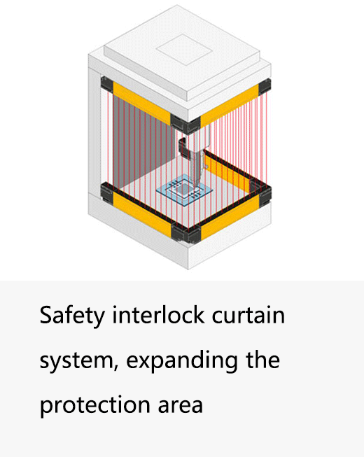
Quick answer: Put the machine in a safe state, preserve the diagnostic code and active configuration, then distinguish an object detection from a sensor or safety-circuit fault. Inspect optics, mounting, supply and model-specific inputs in that order unless the fault code directs otherwise. Correct the cause and verify the safety function before restart. Repeated resets, disabled monitoring or a smaller field are not repairs.
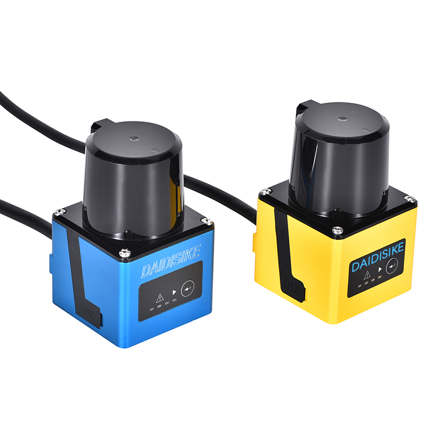
A recurring reset without a recorded cause leaves the next shift unable to distinguish a transient intrusion from a persistent fault. Start by identifying the exact model in the LiDAR model and function overview: ST27 is the confirmed Type 3 / PL d / SIL 2 scanner; DLD, SDLD, DLDS and JPTG are non-safety sensing devices, so OSSD/EDM troubleshooting must not be assumed to apply to them.
This is a working reference for engineers and maintenance teams who are responsible for industrial safety LiDAR scanners installed under IEC 61496-3 with safety functions evaluated to ISO 13849-1. It assumes the scanner is already commissioned and the safety function is documented; what we are dealing with is the year-three reality of dust, vibration, contactor wear and the slow drift that nobody wrote down. The pillar reference across the LiDAR family is our Industrial Safety LiDAR — Complete Reference; if you have not been there, start there and come back.
A failure-mode taxonomy that actually helps
We learnt years ago that the fastest diagnosis comes from deciding which of four buckets the fault is in before opening any wiring panel. Skip this step and you will spend an afternoon checking cables on what turns out to be a dirty window.
| Bucket | Examples | How the scanner tells you |
|---|---|---|
| Optical | Window contamination, fog/dust, ambient IR, retro-reflective surfaces, low-reflectivity targets | Contamination warning, intensity/quality diagnostic, intermittent OSSD |
| Mechanical | Mounting drift, vibration, fixture loosening, impact damage, thermal cycling | Field-boundary drift, alignment warning, sudden onset trips |
| Electrical | OSSD short-circuit, EDM feedback fault, ground loop, broken sync wire, supply ripple | Lockout codes, OSSD test pulse failure, controller event log |
| Logical / configuration | Wrong field set, EDM enabled with no feedback wired, checksum mismatch, response-time mis-set | Lockout on power-up, version/CRC error, refused parameter download |
The taxonomy maps loosely onto the IEC 61496-3 fault model: a Type 3 scanner is expected to detect and respond to its own single faults inside the published fault response time, and any fault it cannot detect must be tolerable in light of the architecture. What that means in practice: the scanner is doing a great deal of self-checking, and most of what you see as a fault is the scanner correctly refusing to keep running.
False trips — the full taxonomy
A “false trip” is a misnomer; the trip is real, but the object that caused it is not what you wanted to protect against. Sorting these out is mostly a question of pattern recognition.
| Trip source | Mechanism | Standard fix |
|---|---|---|
| Precipitation (rain, snow, fog) | Near-range backscatter creates spurious returns | Check diagnostics and model environmental limits; use multi-echo or a hood only where expressly supported and permitted |
| Airborne dust / fines | Same as fog; worse with surface buildup | Clean by the approved method; reassess inspection frequency; add a purge only where the exact manufacturer permits it |
| Low-reflectivity object | Black rubber, dark fabric returns too little energy near field edge | Use scanner with 1.8% remission spec; size the field with margin from the rated range |
| Ambient IR (sunlight, halogen, arc) | Receiver saturation by broadband light | Shroud receiver from direct sun line; relocate or shield arc sources |
| Scanner-to-scanner cross-talk | Adjacent scanner's pulse mistaken for an echo | Apply only the model-supported interference controls; any mounting-plane change requires renewed coverage and stopping validation |
| Retro-reflective / mirror surfaces | Multipath returns from polished floors, glass, mirrors | Matte coating, baffles, rotate scanner; configure reflector blanking only when certified |
| Mounting vibration | Field shifts physically into a static obstacle | Inspect and restore mounting under safe isolation; verify against the approved field before any re-teach |
Optical processing differs by model. Do not assume a multi-echo setting, pulse code or synchronization input exists. Use documented diagnostic indicators to distinguish contamination, interference and low target remission. Environmental filtering may add response time or affect detection; revalidate any permitted change.
Optical contamination — cleaning is a maintenance schedule, not a heroic act
Check whether a cleaning plan exists and whether the specified cleaning method was followed. Missing records make it harder to distinguish normal accumulation, a damaged cover and an unsuitable environment; no customer-investigation history is claimed here.
The scanner already tells you when to clean. Most safety scanners output a contamination percentage or graded warning well before the threshold that trips the OSSD. Log that value weekly for the first two months of operation; you will see the curve characteristic of your environment. Set the cleaning interval at roughly half the time it takes to reach warning, and you will rarely meet the lockout threshold. The naive alternative — cleaning “every Friday” — is either too often (waste) or too rare (lockouts), and almost never matches the actual environment.
Use only the cleaning agent and method listed for the exact optical cover. Do not assume isopropyl alcohol or a sacrificial cover is permitted. Unapproved solvents, films and added windows can damage coatings or change detection. Follow the manufacturer procedure for any replaceable cover, including calibration and functional checks where required.
Mounting alignment drift
Drift is the failure mode nobody schedules for. Vibration over time loosens fixture bolts, thermal cycling on an outdoor or high-bay install shifts brackets by fractions of a degree, and a forklift bump nobody reported moves the scanner enough to send the protective field into a static obstacle. The result is a scanner that worked fine for nine months and now trips regularly.
Three habits prevent most of this. First, stiff brackets: two-point mounting top and bottom, mid-span support on long runs, and torqued fasteners with a thread-locking compound rated for vibration. Second, inspect field stability at the documented interval using a controlled procedure, without exposing people to hazardous motion; investigate flicker at static boundaries. Third, store the original field configuration off the scanner (in the safety-controller backup or a controlled file) so you can compare the live field to the as-commissioned one and detect drift in software, not by intuition. For more on the optical and mechanical alignment routine that applies equally to scanners and curtains, see our companion guide on alignment issues and false trips.
OSSD lockout — what triggers it and how to reset safely
OSSD outputs may use short test pulses to detect output faults. The receiving safety input must be compatible with their voltage, timing and filtering requirements. Do not wire ordinary PLC inputs or contactor coils directly merely because the signal is 24 V. Consult both device manuals; expected diagnostics depend on the actual output and feedback architecture.
- A short between OSSD1 and OSSD2 (cross-fault).
- A short of either OSSD to 24 V or 0 V.
- A downstream switching device (contactor, safety relay) that did not respond as expected.
- An internal driver fault inside the scanner.
Any of these latches the scanner into a lockout. The OSSDs stay off, the diagnostic flags the cause, and the unit will not run again until the cause is cleared and a deliberate reset is issued. This is not a nuisance; this is the scanner doing its job. The reset must come from a monitored input, ideally outside the danger zone and visible to whoever issues it, and it must never be wired through software-only logic that can be bypassed. If a lockout repeats within a few cycles after reset, stop. The unit is telling you something, and pressing the button harder is not the answer.
EDM (External Device Monitoring) failures
External Device Monitoring is the loop that gives the safety function its ability to detect a stuck or welded downstream contactor — a requirement for Category 3 architecture under ISO 13849-1. The scanner switches OSSDs; the contactors switch; their mirror (force-guided) contacts feed back into the EDM input. The scanner expects the EDM input to be the logical inverse of the OSSDs within a configured time window (typically a few hundred milliseconds). If it is not, the scanner locks out with an EDM fault.
The recurring problems with EDM are mundane. First, the contactors used do not actually have force-guided mirror contacts and are using auxiliary contacts that can stay consistent with the main contacts during a weld — that is a hardware error caught only by audit. Second, EDM is enabled in the scanner configuration but the feedback wire is missing or shorted — immediate lockout at power-up. Third, the EDM time window is too tight for the actual contactor response time, especially with large contactors or long wiring runs — intermittent lockouts that look random. Fix the configuration to match the hardware, not the other way round.
Scanner-to-scanner interference
Two scanners pointed into a shared volume can see each other’s emitted pulses. The receiving scanner interprets the foreign pulse as a return from a non-existent object — a phantom intrusion appears in the field, the OSSDs drop, and the trip clears as soon as the units fall out of sync. Classic examples are two fixed scanners covering opposite ends of an aisle, a fixed gate scanner facing an AGV-mounted scanner, or two mobile platforms meeting head-on.
Three mitigations, used in combination on busy sites:
- Geometric offset. Mount adjacent scanners at slightly different heights or angles so the active scan planes do not coincide. A 30–50 mm vertical offset is often enough.
- Pulse coding / modulation. Most modern scanners support several pulse signatures or modulation codes. Assign different codes to scanners that share line-of-sight.
- Hardware synchronisation. Where the scanner family supports it, run a sync wire between fixed units so their scans timeshare the field. This is the most robust answer for static installations and is what we recommend on long aisle protection runs.
Wiring faults — the boring half of every lockout
A surprising fraction of stubborn scanner faults trace back to wiring done weeks earlier and never re-verified. The usual suspects:
- Crushed cables in cable carriers — on AGVs and moving gantries, repeated flex eventually breaks a sync or OSSD conductor. A break that intermittently makes contact is the worst kind because it produces random lockouts.
- Shared 0 V return with inductive loads — valves and contactor coils on the same return as the scanner’s 0 V will inject transients into the OSSD circuit. Use a dedicated return for the safety wiring.
- Cable shield grounded at both ends — creates a ground loop and a path for low-frequency hum that can show up as occasional OSSD test mismatches. Follow the exact device EMC instructions and site equipotential-bonding design; one-end grounding is not a universal rule.
- Parallel routing with motor power — follow manufacturer separation and routing instructions; cross at 90° where appropriate.
Common error categories (generic, not brand-specific)
Specific error codes vary by manufacturer, but the categories do not. Every safety laser scanner’s diagnostic falls into one of these:
| Category | What it means | Typical root cause |
|---|---|---|
| OSSD fault | Self-test pulses on the safety outputs did not return the expected response | Wiring short to 24V, short to 0V, cross-fault between OSSD1/OSSD2, contactor stuck closed |
| EDM fault | External Device Monitoring feedback did not invert when OSSDs switched | Welded contactor, missing feedback wire, wrong EDM enabled/disabled in config |
| Contamination warning / error | Front window optical attenuation exceeds threshold | Dirty or damaged window, condensation, fine surface scratching from abrasive cleaning |
| Internal hardware fault | Diagnostic on motor, mirror, photodiode or supervisor MCU failed | Bearing wear, impact damage, end-of-life, supply transient |
| Configuration / CRC fault | Parameter set checksum or version mismatch | Aborted parameter download, firmware update interrupted, replacement scanner not re-paired |
| Communications fault | Loss of safe network connection or sync line | Cable damage, EMI on the bus, terminator missing, sync wire open |
Diagnostic decision table
Pin this near the scanner. Maintenance teams who carry a version of this on a laminated card resolve faults in minutes instead of shifts.
| Symptom | Likely cause | Next step |
|---|---|---|
| OSSD drops intermittently, scanner clears within seconds, no lockout | Optical false trip (precipitation, dust, low-reflectivity) | Read available model diagnostics; clean by the approved procedure; check supported settings without assuming multi-echo exists |
| Trips correlate with another scanner cycling in the same aisle | Scanner-to-scanner interference | Apply manufacturer-permitted interference controls; preserve and revalidate required field coverage |
| Lockout immediately at power-up | Configuration CRC, OSSD wiring fault, or EDM mis-enabled | Read diagnostic code; verify configuration version against drawing |
| Lockout after first machine cycle, EDM error | Contactor feedback not inverting in expected time window | Scope feedback signal; check K1/K2 mirror contacts; verify EDM timeout setting |
| OSSD switches off when drives start | EMI on OSSD or sync wiring, ground loop, supply ripple | A qualified person should check supply, routing and bonding against the equipment manuals under a safe test procedure; do not assume a universal ground or filter arrangement |
| Gradual rise in contamination warning over weeks | Window soiling at rate exceeding cleaning interval | Shorten interval; check window cover integrity; review environment |
| Field intrusion reported with no visible object | Specular reflection, hanging cable, mounting drift | Use the prescribed test object with hazardous motion prevented; inspect mounting and geometry, and review any re-teach against the required approved field |
| Persistent contamination error after thorough clean | Window damage (scratching, hazing) or internal optics fault | Inspect window under raking light; if scratched, replace cover or scanner |
Preventive maintenance — a realistic schedule
The following is a planning example, not a universal inspection interval. The device manual, risk assessment and local operating conditions determine the required checks:
- Weekly: inspect the window and available contamination diagnostics; carry out the manual's prescribed test-object procedure and complete coverage checks with hazardous motion prevented.
- Monthly: clean window per manufacturer procedure, verify bracket fasteners are still at torque, review controller event log for recurring warnings that did not become lockouts.
- Quarterly: review the required functional-test plan. Any dynamic stop, fault-response, feedback or restart testing must follow the exact system manuals and an authorized controlled procedure without exposing people to hazardous motion; do not assume every scanner supports EDM.
- Annually: compare live field configuration against the as-commissioned backup; inspect cabling at moving sections; verify response time of the whole chain still meets the ISO 13855 distance calculation.
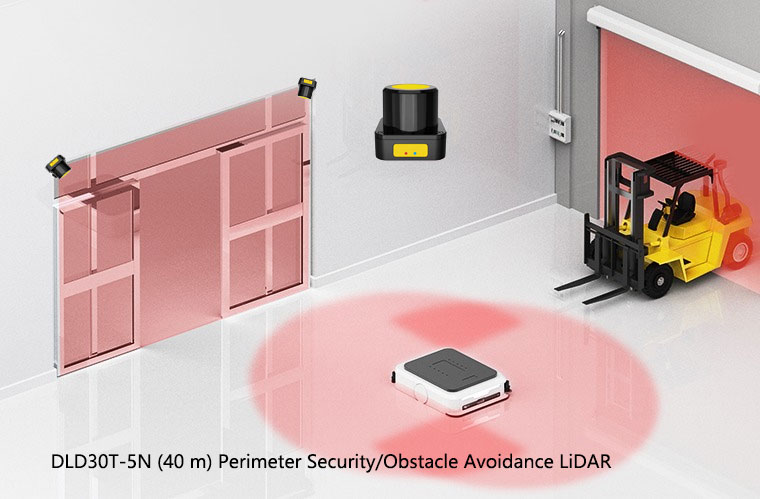
For harsher exposure, determine shorter inspection or cleaning intervals from the manual and observed contamination, not a universal multiplier. DLD30T-5N is non-safety perimeter measurement LiDAR; confirm its environmental limits before outdoor use and keep its maintenance requirements separate from those of a safety scanner.
When to replace rather than repair
A safety laser scanner is a sealed, type-approved assembly. Field repair beyond replacing the front window cover, mounting hardware and external cabling is not appropriate — any internal change can invalidate the IEC 61496-3 certification. Remove the device from service and obtain the manufacturer's repair or replacement decision when:
- The diagnostic shows a hardware fault that survives a full power-cycle and a known-good configuration download.
- The contamination warning persists after thorough cleaning of an undamaged window.
- The housing has taken an impact hard enough to move the mirror or motor assembly.
- The declared service-life limit requires replacement. A proof-test interval instead requires the specified test; it is not automatically an end-of-life limit.
Document every swap with serial numbers, the date, and the configuration version restored to the replacement unit. Replacement traceability is a routine audit question under IEC 62046 and the answer should not be “we think it was last winter.”
The bottom line
Safety laser scanners earn their certification by being paranoid on your behalf. The cost of that paranoia is more diagnostic noise than a simpler sensor would generate, and every code is worth reading before it is cleared. If the team treating “press reset, line runs” as the entire maintenance procedure starts treating the diagnostic log as the entire maintenance procedure, both uptime and audit posture improve at the same time. That is, in the end, what the standard intended.
References
- IEC 61496-3:2025 — Safety of machinery: Electro-sensitive protective equipment, Part 3: Particular requirements for active opto-electronic protective devices responsive to diffuse reflection (AOPDDR).
- ISO 13849-1 — Safety of machinery: Safety-related parts of control systems. Fault response, diagnostic coverage and Performance Level architecture for Category 3 and 4 systems.
- IEC 62046:2026 — Safety of machinery: Application of protective equipment to detect the presence of persons. Verification and maintenance requirements.
- ISO 13855 — Positioning of safeguards with respect to the approach speeds of parts of the human body. The safety-distance calculation that ties scanner response time to mounting geometry.