
The starting point
The cell in this example is a common one: a single welding robot, a two-station turntable or fixture, a part conveyor, and a fixed steel fence with one interlocked access gate. Cells like this were built in large numbers and many are still running. They were not unsafe by the standards of their day. But two problems tend to surface as they age.
The first is nuisance trips. An older protective device near a welding arc — or a curtain mounted without much thought to arc light and reflective workpieces — trips when nothing is wrong. Every false stop costs cycle time and, worse, trains operators to see the safety system as an obstacle. The second is access behaviour. When the only way in is one slow interlocked gate, operators under throughput pressure start finding workarounds: reaching over the fence, propping the gate, climbing in for a quick fixture tweak. Both problems point at the same fix — safeguarding that matches how people actually use the cell.
The brief
A retrofit like this usually has three goals stated together: bring the cell up to current robot-cell safeguarding practice (the kind of layered approach ISO 10218-2 expects, with ISO 13855 distances), cut the nuisance trips, and do not lose cycle time. That last one matters — a safety upgrade that slows the line will be resented and undermined. Good safeguarding has to be the easy path, not the obstacle.
Step 1 — Map the access routes
The assessment always starts the same way: walk the cell and list every route a person can take to reach the robot. In a typical welding cell that is the operator load and unload opening, the open floor space at the side or rear used for maintenance, and the conveyor aperture where finished parts leave. Each route is a different geometry, and that is what decides the device.
Step 2 — Area light curtain on the load opening
The operator opening is a defined plane: compare access-protection light curtain configurations against its detection height, resolution and required safety performance. DQSA is a candidate area / body-detection family, subject to the exact model documentation and complete safety-function validation. If material must pass through the protected opening, design muting in compatible safety logic; the sensor sequence is not proof that an object is a part rather than a person. Restrict the aperture, validate load gaps and following access, and ensure a fault or timeout restores protection.
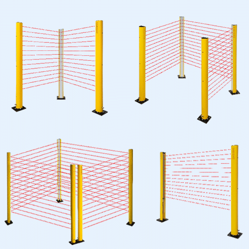
The arc-interference problem is handled here, at selection and mounting. A Type 4 light curtain uses modulated, coded infrared beams, but the Type classification does not guarantee immunity to every arc or reflection. Test the specified ambient-light limits on site. The curtain is positioned outside the direct spatter throw and oriented away from the arc, and the mounting distance is set by the ISO 13855 calculation — the cell stopping time, the device detection capability and the approach-speed constant decide how far back the plane sits. The bracket position follows the calculation, never the other way round.
Step 3 — Safety laser scanner on the floor zone
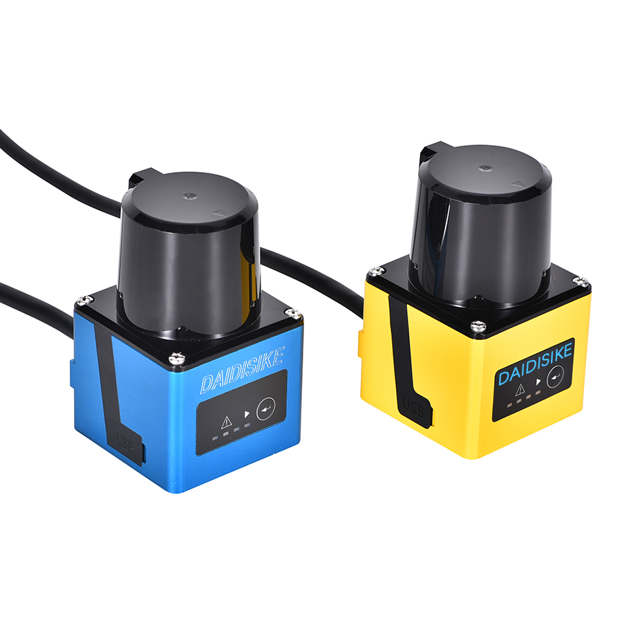
A light curtain plane cannot cover the open floor space beside or behind the cell. This route needs a certified safety scanner if it commands a protective stop. DAIDISIKE confirms ST27 as Type 3, PL d, SIL 2; select its exact configuration and field coverage against the risk assessment. DLD is non-safety LiDAR and cannot replace that function. A warning field may provide information; any credited slowdown must use validated safety signals and logic.
Step 4 — Tie it together and verify
Both devices feed the cell safety logic, which commands the robot and the welding equipment to a safe state. The whole safety function — sensor, logic, final actuator — is verified against the required Performance Level from the risk assessment; a Type 4 curtain on its own does not make the function PL e if the logic or the actuator drags the chain down. Stopping time is measured on the real cell, the ISO 13855 distances are confirmed against that measurement, and the modification is documented: a fresh risk assessment for the changed function, kept on file, and assess the legal consequences separately under Articles 3(16) and 18 of the Machinery Regulation when that regime applies.
Typical results
Evaluate these outcomes during acceptance and the agreed observation period; no measured results are available for this illustrative case:
- Nuisance trips: log receiver faults, arc conditions and contamination before and after the change.
- Cycle time: compare equivalent operating modes, parts and shifts; count planned stops separately.
- Access behaviour: observe foreseeable bypass attempts and confirm every access route remains protected.
- Validation record: retain measured stopping time, field tests, reset checks and safety-function verification.
What makes this kind of retrofit work
This design exercise starts with access routes, then assigns an appropriate protective device to each route. The welding interference troubleshooting guide helps distinguish optical faults from wiring and alignment problems. The ISO 10218-2:2025 application and integration scope is the starting point for robot-cell requirements; the project still needs its own validation evidence.
Related reading
Light Curtain vs Scanner for Robot Cells
Perimeter plane versus area zone — choosing safeguarding for a robot cell.
Ghost Trips in Welding Cells
Handling optical interference from arc light and reflective surfaces.
DAIDISIKE DQSA Area Light Curtain
Area / body-detection light curtain for robot-cell access guarding.