
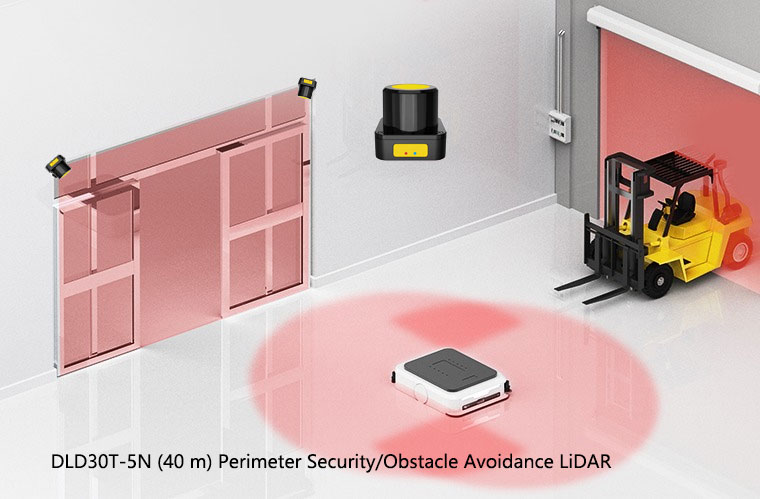
The category has matured. Ten years ago a serious safety laser scanner was a heavy, expensive, indoor-only device that lived on a handful of high-end AGVs and a few robot cells. Today it ships in volume on every credible mobile robot, guards perimeters that used to need fences and beams, and sits inside collaborative cells that would have been impossible a decade ago. The physics has not changed much. What has changed is integration, price and configurability — and that has made selection easier in some ways and far harder in others. This article is the long-form reference we write to settle the recurring questions in one place.
How a safety LiDAR actually measures distance
A safety LiDAR is fundamentally a ranging device. A laser source emits short, modulated infrared pulses; the scanner times how long the light takes to bounce off whatever is in front of it and return. Multiply by the speed of light, divide by two, and you have a distance. Sweep the beam through an angle and you have a two-dimensional contour of everything in the plane. That is the whole idea — the rest is engineering.
Two ranging techniques dominate industrial safety LiDAR:
- Direct time-of-flight (dToF) — the workhorse of long-range scanners. A short pulse goes out, an avalanche photodiode catches the return, the time is measured to nanosecond resolution. dToF tolerates longer ranges and lower-reflectivity targets, which is why it dominates perimeter and outdoor applications.
- Phase-shift — a continuously modulated beam where the phase difference between transmitted and received light encodes distance. Phase-shift can be very precise at shorter ranges and is common in compact indoor obstacle scanners. It has tighter range limits than dToF, which is part of why a 30 m perimeter unit and a 5 m AGV unit look like different products inside.
A rotating optic — usually a mirror or, in newer designs, a solid-state deflector — sweeps the beam through an angular field of view, commonly around 270 degrees. The scanner reports range and angle for every increment, builds a 2D contour several times per second, and compares that contour against the user-configured fields. The scan rate (often 15 to 50 Hz) sets a floor on how quickly the device can react; combined with the internal processing time, it determines the response time on the datasheet — the number that goes straight into your safety distance calculation.
The safety-versus-navigation distinction — this is the buyer point
The most expensive mistake in this category, by a long way, is buying a navigation LiDAR and trying to use it as a safety device. The two units look similar. They share the measurement physics. They are sold in the same trade-show aisles. They are not the same thing.
A safety laser scanner is a certified protective device. It is type-tested to IEC 61496-3. It implements internal diagnostics that catch its own faults. It outputs dual, redundant, self-monitored OSSD signals that a safety controller can trust. It has a defined detection capability — the smallest, darkest target it is guaranteed to see — and a rated response time you can put into a stopping-distance calculation. It can carry a declared Performance Level or SIL contribution under ISO 13849-1 or IEC 62061.
A navigation LiDAR is a sensing device. It maps, it localises, it feeds the SLAM stack, it gives a vehicle general obstacle awareness for path planning. It is often very accurate and very useful. It is not certified. It has no OSSD outputs. It must never sit in the protective layer that keeps people safe.
A modern AGV typically carries both: one or more navigation LiDARs for driving, plus one or more safety laser scanners for the protective field. That is the correct architecture. What is not correct is letting the navigation sensor stand in for the safety one, no matter how good the navigation LiDAR looks on paper.
The standards landscape, in plain English
A safety laser scanner sits inside a layered standards stack. The short version is below; the full text lives at iec.ch, iso.org and automate.org. We link to the cluster sibling on IEC 61496-3 explained for a deeper read.
| Standard | What it covers | Why it matters for a LiDAR |
|---|---|---|
| IEC 61496-1 | General requirements for electro-sensitive protective equipment (ESPE) | Sets the umbrella safety, diagnostics and immunity rules |
| IEC 61496-3 | Particular requirements for active opto-electronic protective devices responsive to diffuse reflection (AOPDDR) — i.e. safety laser scanners | This is the product standard. A scanner without IEC 61496-3 type approval is not a safety device. |
| IEC 62046 | Application of protective equipment to detect persons | How to install and configure detection devices in a real machine layout |
| ISO 13855 | Positioning of safeguards with respect to approach speeds of parts of the human body | Supplies the formulae for fixed-station safety distance |
| ISO 13849-1 | Safety-related parts of control systems — Performance Level (PL) | How the scanner’s safety rating combines with logic and actuator to give the function PL |
| IEC 62061 | Functional safety of safety-related control systems (SIL) | The SIL counterpart to ISO 13849-1, frequently used in heavy industry |
| ISO 3691-4 | Driverless industrial trucks and their systems | Governs AGV integrated safety functions, including detection distances |
| ANSI/RIA R15.08 | Industrial mobile robots (IMR) — North American standard | The North American counterpart for AMR safety; applies to scanner integration on those vehicles |
| IEC 60825-1 | Safety of laser products (laser classification) | Almost all safety LiDARs are eye-safe Class 1; the standard sets that limit |
The chain that matters most: IEC 61496-3 says whether the device itself is a safety scanner. ISO 13849-1 or IEC 62061 says whether the whole function — scanner plus logic plus actuator — reaches the PL or SIL your risk assessment requires. A Type 3 scanner with PL d on the datasheet is not automatically a PL d function; the safety logic and final element have to support it. This is one of the things auditors check.
Type 3, Type 2, and what AOPDDR classification means
IEC 61496-3 classifies AOPDDR devices into Types. The two categories you will routinely see on safety scanner datasheets:
- Type 2 — suitable for applications where the risk assessment calls for up to PL c per ISO 13849-1. Single channel with periodic testing.
- Type 3 — the workhorse classification for safety laser scanners. Dual-channel architecture with continuous self-test, suitable for applications up to PL d. The great majority of industrial safety LiDARs you will compare are Type 3 devices.
Type 4 in IEC 61496 exists for through-beam and reflective light curtains, not for AOPDDR scanners; if you see “Type 4” claimed on a scanner datasheet, look closely — the device may be referencing a different part of the standard or a different functional sub-assembly. For an AOPDDR safety LiDAR, Type 3 is the ceiling and PL d is the achievable Performance Level for the detection itself.
Protective field, warning field, and field-set switching
A safety laser scanner monitors a 2D zone across the floor — a slice of space at the scanner’s mounting height. That zone is configured as nested fields. There is no fixed number of fields; modern scanners typically support dozens of configurable zones organised into field sets.
The two fundamental zone types:
- Protective field — the inner, safety-rated zone. Anything detected inside it switches the OSSD outputs to the off state and the machine stops. This is the field whose length and shape your safety distance calculation pins down.
- Warning field — the outer, non-safety zone. An intrusion here triggers a soft reaction: a slowdown, an audible alert, a beacon. The warning field exists to keep the machine productive by reacting to approaches before they become stops.
On an AGV, the relevant protective-field length is a function of vehicle speed, since stopping distance grows with speed. A well-configured AGV therefore carries several field sets — a long protective field for high speed, a shorter one for slow travel, narrower ones for turning — and switches between them in step with the drive controller. Field-set switching is where a basic installation becomes a usable one. The cluster sibling on multi-zone protective field configuration goes deep on the geometry and the switching signals; the AMR fleet field-switching article covers the fleet-level traffic considerations.
Range classes — matching the scanner to the application
Range is the spec everyone reads first and the one that most often gets oversized. The protective range must comfortably exceed the machine’s worst-case stopping distance, with margin for response time and reaction delays. Beyond that, more range mostly adds cost and brings in background clutter you then have to mask out.
| Range class | Typical protective range | Application fit | DAIDISIKE example |
|---|---|---|---|
| Compact AGV | ~5 m | Small AGVs, tight aisles, indoor logistics tugs | DLD05A3 |
| Mid-range TOF | ~14 m | Mid-size AGV hazard areas, medium cells, intralogistics | SDLD-05A TOF scanner |
| AMR / large area | ~20 m | Faster AMRs, larger area guarding, mixed indoor traffic | DLD20A5 |
| Perimeter / long range | 40 m and beyond | Fence-line security, vehicle lane separation, outdoor boundaries | DLD30T-5N perimeter LiDAR |
The right way to use this table is from the right column outward. Start with the application, then read the realistic protective range, then look at what is available in that class. Starting from the “biggest number on the datasheet” column produces oversized, expensive installations that nuisance-trip more, not less, because they pick up clutter the application never needed them to see.
Application categories — where scanners actually go
AGV obstacle avoidance
The single largest deployment volume for safety laser scanners. Front-mounted on the direction of travel, configured with field sets that change with vehicle speed and turning state, integrated with the drive controller via OSSDs or a safety bus. Compact 5 m to 14 m scanners dominate; what matters is response time, field switching, and the smallest reliably detected object on the floor.
AMR area protection
AMRs travel further and faster than classic AGVs, share floors with humans more freely, and often carry multiple scanners for 360-degree coverage. The 20 m range class is the home territory. The dedicated article on safety LiDAR for AMR fleets covers the multi-vehicle coordination, traffic zones and field-switching strategies in detail.
Fixed perimeter security
Long-range scanners replacing or augmenting fences and beam systems — substation boundaries, yard perimeters, asset enclosures. Different product class to indoor units: tighter IP rating, fog and rain immunity, longer protective range. See the companion piece on outdoor perimeter safety LiDAR for the environmental engineering.
Vehicle lane separation and gates
Mid-range to long-range scanners watching the gap between people and forklift traffic, or guarding a controlled gate from tailgating. Often combined with traffic-light signalling and motion controllers.
Robot cell area guarding
For cells where the protected geometry is an irregular floor zone, a scanner does what a flat light curtain cannot. Walking access, multi-side approach, large pick-and-place envelopes — these are scanner jobs. Where the access is a clean opening, a light curtain is still the cleaner answer. We come back to this trade-off below.
Mounting fundamentals — height, tilt and blind zone
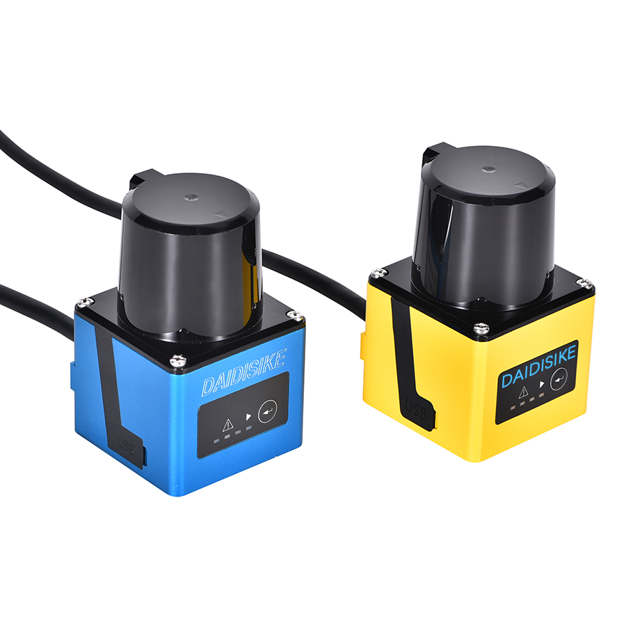
Mounting decides whether a scanner sees a person or trips on a floor seam. Three numbers drive the geometry:
- Mounting height — the scanner’s plane of detection. Common AGV mounting is around 150 to 200 mm above the floor, low enough to catch feet and ankles. Mount too high and a person lying or kneeling is invisible; mount too low and normal floor unevenness becomes a phantom obstacle.
- Tilt — deliberate or accidental inclination of the detection plane. Even small tilts project the plane into the floor or above the target body part at range. Where tilt is unavoidable, it must be designed in and compensated; where it is accidental, it is a defect.
- Blind zone (dead zone) — the close-in range where the scanner cannot resolve a return, plus the angular shadow behind the device housing. Both are part of the installation geometry. A scanner mounted at the front of an AGV has a shadow behind it; that shadow is somebody else’s scanner’s job to cover.
The mounting article in this cluster — safety laser scanner mounting, tilt angle and blind spots — walks through real installation geometries, including how to combine multiple scanners for 360-degree vehicle coverage without leaving a corner uncovered.
Environment — what the IP rating and the optics have to handle
A safety LiDAR is a precision optical instrument behind a polymer window in an industrial environment. The environment will attack it. Plan for that.
| Environment | Key concern | Selection guidance |
|---|---|---|
| Clean indoor factory | Dust accumulation on the optical window | IP65-class enclosure; cleaning protocol |
| Heavy industrial indoor | Oil mist, weld spatter, conductive dust | Higher IP rating; shielded mounting; consider protective skirts |
| Cold store / freezer | Condensation when cycling in and out | Operating temperature spec to the lower limit; heated window if available |
| Outdoor perimeter | Rain, fog, snow, direct sun, contamination | Outdoor-rated scanner with fog/rain immunity; not an indoor unit relabelled |
| High ambient light | Sun glare, halogen, weld arc | Modulated source with strong ambient-light rejection; verify on datasheet |
A small but useful detail: laser safety. Industrial safety LiDARs are almost universally classified as eye-safe Class 1 under IEC 60825-1. That means the laser cannot exceed accessible-emission limits under reasonably foreseeable conditions of use; you do not need eye protection in front of a Class 1 scanner. It is worth confirming on the datasheet, especially for very long-range outdoor units.
Failure modes — how scanners actually go wrong
A short field guide to what trips, why, and what to do about it. The full troubleshooting article — failure modes and troubleshooting — goes into the diagnostic detail and the fixes; the summary below is the orientation.
- Window contamination. By a margin, the most common cause of nuisance stops. Dust, oil mist, sticker residue and condensation on the optical window all attenuate the laser return; once attenuation crosses the device threshold, the scanner faults to safe and the machine stops. Solution: scheduled cleaning, intelligent placement away from spatter sources, and a sensible operator response when the contamination alert appears in the warning band before it becomes a hard fault.
- Alignment loss. A bumped scanner is a misaligned scanner. Field geometry that was carefully commissioned now points slightly off. On a vehicle this often shows up as one specific docking station becoming unreliable. Solution: robust, repeatable mechanical mounting, and a re-verification step after any maintenance that involved touching the device.
- Field-set selection errors. When the AGV does not signal its state cleanly to the scanner — wrong field set selected at the wrong time — the protective field is either too short for the vehicle’s actual speed or too long for the corridor it is in. Solution: verified safe input handling, periodic functional tests, and clear state machines on the vehicle controller.
- Optical cross-talk. Two scanners pointing at each other on facing AGVs can in principle interfere. Modern safety scanners use coded pulses and ambient-light rejection to suppress this, but a poorly designed fleet layout can still create marginal cases. Worth checking when commissioning a multi-vehicle area.
- Background reference loss. Some applications use the scanner to monitor a fixed background contour — for example, a fence line — and trigger when that background changes. Slow background drift, vegetation growth outdoors, or accidental object placement can all cause a background reference fault that looks like an intrusion. The cure is application-aware setup.
When a light curtain still wins — the honest comparison
A safety laser scanner is not a universal replacement for a safety light curtain. They guard different shapes, and a well-designed installation often uses both.
| Application | Light curtain | Safety laser scanner |
|---|---|---|
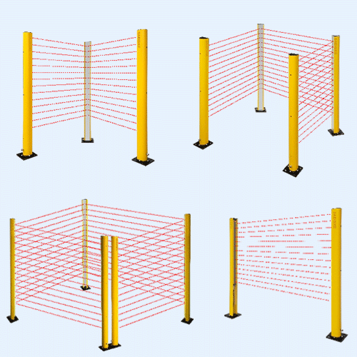
| Defined vertical access (door, opening) | Natural fit — one beam plane, deterministic resolution | Overkill, harder to commission for a simple opening |
| Open floor area, multi-side approach | Hard — needs many curtains and corner units | Natural fit — 2D zone, single device |
| Point-of-operation finger/hand detection | Natural fit — 14 mm finger resolution is standard | Not suitable — angular resolution does not match finger detection |
| Moving vehicle (AGV/AMR) | Not suitable | Natural fit — horizontal floor zone, field switching |
| Perimeter, long distance | Limited — through-beam at very long ranges is awkward | Natural fit — 40 m+ scanners purpose-built for this |
| Combined access opening + walk-in area | Part of the answer | Part of the answer — use both |
The right question is not “curtain or scanner.” It is “what is the shape of the space I have to protect, and what are all the routes a person can take to the hazard.” Decide by geometry, not by which technology is newer.
The DAIDISIKE LiDAR product family — brief and neutral
Since this is the DAIDISIKE site, a short reference to our own scanner line so it sits in context:
- DLD05A3 — 5 m class obstacle-avoidance scanner for compact AGVs and tight-aisle indoor work.
- SDLD-05A — 14 m TOF safety laser scanner for mid-size AGV hazard areas and medium cells.
- DLD20A5 — 20 m class scanner for faster AMRs and larger floor zones.
- DLD30T-5N — 40 m perimeter security and obstacle-avoidance LiDAR for fence lines, lanes and outdoor boundaries.
Around the scanner line sit the safety light curtain families (DQA, DQC, DQT4, DQE, DQO, DQSA, DQR, MK, JER), proximity and laser sensing, and the DA31 safety relay for OSSD evaluation and logic. The right device for a job is the right device — where a light curtain is the cleaner answer, that is what we say.
How to specify a safety LiDAR — the working checklist
- Confirm the device is a certified safety LiDAR (IEC 61496-3 Type 3), not a navigation LiDAR.
- Establish the required Performance Level or SIL from the risk assessment. Confirm the scanner’s rated contribution supports it.
- Compute the worst-case stopping distance for the machine or vehicle. Pick a range class that comfortably covers it across all speeds and states.
- Design the protective field and warning field for each operating state. Plan field-set switching with the controller.
- Match the environmental rating to the worst real environment the device will see — not the average one.
- Fix the mounting geometry: height, tilt, blind zone and multi-scanner coverage if applicable.
- Verify response time fits the ISO 13855 or ISO 3691-4 calculation, including controller and brake delays.
- Validate the whole safety function — scanner + logic + actuator — achieves the required PL or SIL, and document the verification.
References & standards cited
- IEC 61496-1, Safety of machinery — Electro-sensitive protective equipment — Part 1: General requirements and tests. Published by the IEC, iec.ch.
- IEC 61496-3, Particular requirements for active opto-electronic protective devices responsive to diffuse reflection (AOPDDR). iec.ch.
- IEC 62046, Safety of machinery — Application of protective equipment to detect the presence of persons. iec.ch.
- ISO 13855, Safety of machinery — Positioning of safeguards with respect to the approach speeds of parts of the human body. iso.org.
- ISO 13849-1, Safety-related parts of control systems — Part 1: General principles for design. iso.org.
- IEC 62061, Functional safety of safety-related control systems. iec.ch.
- ISO 3691-4, Industrial trucks — Safety requirements and verification — Part 4: Driverless industrial trucks and their systems. iso.org.
- ANSI/RIA R15.08, Industrial mobile robots — Safety requirements. Published by the Association for Advancing Automation, automate.org.
- IEC 60825-1, Safety of laser products — Equipment classification and requirements. iec.ch.
Related reading
Deeper into the cluster
IEC 61496-3 Explained
What the standard actually requires of an AOPDDR safety scanner.
Multi-zone Protective Field Configuration
Designing nested fields and field-set switching for variable speed.
Mounting, Tilt and Blind Spots
Height, tilt, dead zone and the geometry that makes or breaks a scan.
Failure Modes & Troubleshooting
Contamination, alignment loss, false trips and how to fix them.
Outdoor Perimeter LiDAR
Long-range, weather-immune scanners for fence-line protection.
Safety LiDAR for AMR Fleets
Field switching, traffic coordination and protective-field design across a fleet.