
Why solar lines are different from automotive or electronics
A safety engineer who has wired up automotive body shops and SMT lines walks into a modern PV module factory and finds something familiar and something strange at the same time. The familiar part: robots, conveyors, light curtains, the usual ISO 12100 risk assessment vocabulary. The strange part: the units of work are enormous fragile glass sheets, the cycle time is measured in tens of seconds for a whole module, the line stretches well over a hundred metres, and every station was bought from a different supplier.
Three things make PV module manufacturing distinct as a guarding problem.
It is a chain of machines from different builders. A typical line stitches together a stringer from Wuhan Dr Laser or Suzhou Maxwell, layup and bussing from Mondragon Assembly or Jonas & Redmann, a Schmid or Burkle laminator, framing from Reis Robotics or domestic equivalents, EL testers from Halm or domestic builders, and IV/flash testers from Spire or Pasan. Each delivers a CE-marked machine to its own scope. The interfaces between them are the audit hot spots.
Cell technology changed faster than the line did. The industry shifted from PERC to TOPCon majority across 2024-2025, with HJT growing as a premium tier and back-contact cells appearing in newer projects. Most of those changes affect cell handling more than module assembly — thinner wafers, more delicate metallization, tighter optical inspection — but they put pressure on the same stations where operators interact most: stringer load, layup rework, EL inspection. Guarding designed for a 2020 PERC line is not automatically fit for a 2026 TOPCon line.
The 2025-2026 overcapacity has not stopped new lines. Even with widely reported module-price pressure and consolidation among the smaller players, capacity additions from LONGi, JinkoSolar, Trina, JA Solar and Canadian Solar continued through 2025, and several second-tier builders pushed into TOPCon retrofits. New gigafactory lines are still being commissioned in 2026, which is why this guidance is useful now rather than three years from now.
Walking a TOPCon module line, station by station
1. Cell sorting and visual / EL inspection
The line begins with incoming cells being graded by colour, current and electroluminescence response. The hazards here are mild — mostly the cell-handling shuttle and the suction-cup pickup head — but the station is not zero-risk because operators reach into the input tray area to top up cells. A modest body-access curtain at the operator side, paired with fixed guards over the shuttle travel, is the normal answer. Resolution of 30-40 mm hand detection is typical; finger-level resolution is overkill here.
2. Stringer / tabbing — the most hazard-dense station
The stringer is where guarding really matters on a PV line. A modern stringer picks individual cells, applies flux to the ribbon interconnect, and bonds the ribbon to the cell either by infrared lamp soldering or, increasingly on TOPCon and HJT lines, by laser welding. Throughput is typically 6,000-12,000 cells per hour per stringer, which means the cell pickup head, the ribbon feed, the shuttle and the soldering or welding head are all moving fast and close together.
The hazards layer up here in a way they do not elsewhere on the line. There is the obvious pinch and crush from the moving heads. There is the IR lamp or laser energy itself, which on HJT lines is usually low-temperature soldering or infrared reflow rather than high-power laser cutting, but still a burn and eye-safety concern if a guard is open. And there is flux fume, which is a ventilation problem rather than a machine-safety one but is worth mentioning because it influences how the enclosure is built.
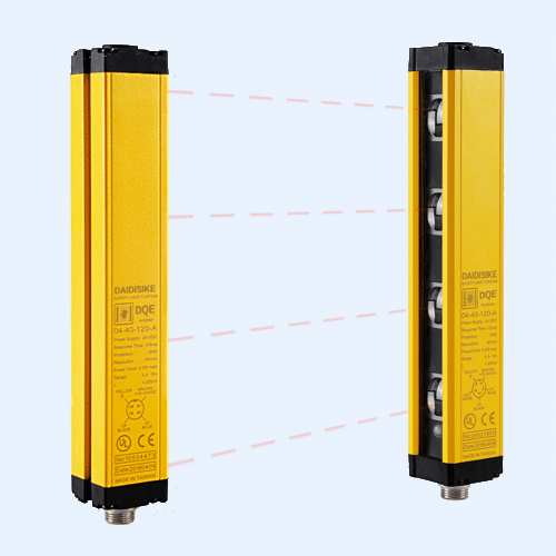
The standard guarding answer is a fully enclosed stringer cell with interlocked sliding doors on the operator side. A Type 4 light curtain at the cell-tray load face, 14-20 mm resolution where an operator places trays by hand, gives access detection without requiring the doors to be opened on every refill. For the larger access doors used during ribbon changeover and head maintenance, a guard-locking interlock is the right tool, because the soldering head and the cell-handling motion need to coast and cool before the door can safely open. Our DX series safety door locks are designed for exactly this duty.
3. Layup and bussing — mass plus fragility
Layup is where the module starts to look like a module. A backsheet or rear glass sheet is placed on a layup tray; an EVA or POE encapsulant sheet on top; the cell-string matrix on top of that; another encapsulant sheet; then the front glass. Bussing ribbons are soldered or welded to connect the strings into a series-parallel matrix. Robots and gantries do most of the heavy lifting; operators handle alignment correction, ribbon rework, and occasional manual placement of edge cells.
The dominant hazards are crush from the glass-handling gantry, pinch at the matrix transfer, and a real but under-discussed hazard: operator reach-in to correct a misaligned cell string. That last one is the source of most layup near-misses we hear about, because the temptation is overwhelming when a small fix would prevent a whole panel from being scrapped, and the enclosure design has to anticipate it rather than rely on discipline alone.
We typically see 30-40 mm body-access light curtains across the operator-facing edge of the layup cell, with a clearly designated rework station where the operator can request a controlled stop and gain safe access through an interlocked door. The back side of the glass gantry, where wrap-around fencing would block conveyor flow, is a good fit for a horizontal area-protection curtain or a safety laser scanner protecting a defined floor zone.
4. Pre-EL test — small machine, real electrical hazard
Before the laid-up sandwich heads into the laminator, most lines run a pre-EL test to catch broken cells or misaligned strings while they are still rework-able. Mechanically the station is modest — a darkened bonnet that closes over the module while a cooled NIR camera images it — but the electrical hazard is real, because EL testing forward-biases the module to roughly its rated voltage to drive the luminescence. For a typical 72-cell or 144-half-cell TOPCon module, that is 40 V DC or more under load, with current in the order of the module Isc.
Machine safety covers the bonnet motion and the door interlock that prevents access while bias is applied. Electrical safety covers the bias supply, the bleed circuit and the lockout-tagout procedure. We see procurement teams pick one and assume it does the work of both; it does not. A safety light curtain at the bonnet load face, plus an interlock that guarantees bias is removed and the module is shorted before the bonnet can open, is the right combination.
5. Lamination — slow, hot, large, and routinely misunderstood
The laminator is the longest-cycle station on the line and one of the most distinctive. It is not a stamping press. It is a large-platen vacuum bonding machine that holds the module at 145-160 degrees C (for EVA; higher for POE) while encapsulant cross-links. Platen sizes for current M10 and G12 modules sit around 2.4 m by 1.4 m. Cycle time is 8-15 minutes including the vacuum hold.
Because the platen closes slowly, the ISO 13855 safety distance calculation is relatively forgiving — but the hazard set is unusual. The platen closing motion is a slow but very high-area pinch. The platen surface is a serious burn risk even when the press is fully open and cooling. The load and unload shuttles move modules in and out at speed and are the more common mechanical hazard in day-to-day operation.
Guarding here is layered. Fixed thermal shielding around the platen edges, an interlocked guard door with an acknowledge required while the platen is above a safe-touch threshold, and a light curtain at each shuttle face protecting the load and unload motion. We have seen sites try to use a single light curtain as the only safeguard on a laminator; that is fine for the shuttle motion but completely ignores the thermal hazard, and it is one of the audit findings we see most reliably.
6. Trim, framing and junction box
After lamination the module is trimmed of excess encapsulant, framed in anodized aluminium, and fitted with a junction box. These are the stations where the line starts to feel like a metal-fabrication shop again, and the hazards are correspondingly familiar.
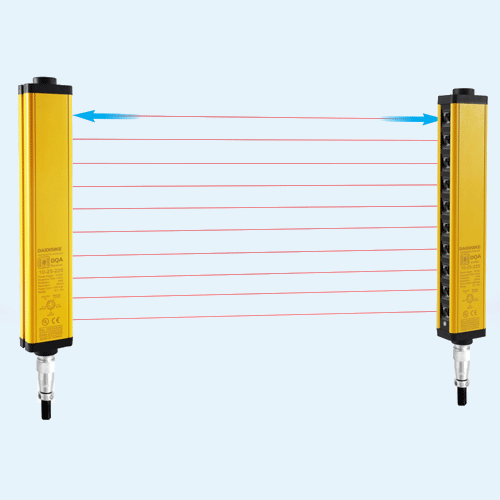
Trim involves cutting tools moving along the module edge — a straightforward laceration and pinch hazard, guarded with fixed enclosure plus light curtains at any operator-facing edge. Framing is a multi-axis robotic operation that presses extruded aluminium profiles around the module edges; the hazard is the framing head closing on the profile, with the operator usually loading framing strips into a magazine. A robotic framing cell guarded as a single robot envelope, with access-detection light curtains and a muted pass-through for the module conveyor, is the normal pattern. Where the cell is large or irregular — some builders integrate trim, framing and J-box mounting into a single island — an area light curtain such as our DQSA or a safety laser scanner covers what a flat curtain cannot.
The junction box itself is fitted, potted with silicone, and the interconnect ribbons soldered or pressed in. Soldering generates local fume and a small burn hazard; potting introduces solvent and dispensing hazards; and on lines that automate J-box mounting fully, a small dedicated robot handles the placement. Light-curtain access detection on the operator side and an interlocked door on the dispenser side cover most of this.
7. Curing oven
After the junction box silicone is dispensed, modules pass through a curing oven held at a moderate temperature for a defined dwell. The mechanical hazard is mostly the conveyor motion entering and leaving the oven. The thermal hazard is real but contained inside the tunnel. Guarding is usually fixed enclosure with interlocked end doors and limited operator access. A light curtain at the operator loading face — if the line uses one — is sized for access detection rather than point-of-operation.
8. Post-EL and flash / IV test
The finished module is EL-tested again to catch any damage introduced during lamination and framing, and then flash-tested on an IV tester — a calibrated solar simulator that measures the module’s current-voltage curve under a standardised pulse of light. The flash itself is short (typically 10 ms class A+A+A+ pulse) but the optical energy inside the test enclosure is significant, and direct viewing is an eye hazard.
Guarding here is enclosure-and-interlock. The flash tester is built as a sealed chamber with an interlocked access door; the module enters and exits on a conveyor. A light curtain across the conveyor opening, sized to detect a person but not the module, with appropriate muting, is the normal pattern. The electrical safety considerations are the same as for pre-EL — the module is biased during EL, and there is a meaningful DC source in the test fixture during IV.
9. Final pack and palletising
The end of the line packs modules vertically into cardboard or wooden crates, often with a small palletising robot stacking the finished crates. This is the lightest station for safety — access-detection light curtain, response-time verified, with a muted conveyor pass-through where the empty crates feed in. Palletising has its own subtleties around stopping time and reach distance; we wrote a focused guide to light curtains for automatic palletising systems that applies directly here.
The PV-line guarding cheat sheet
| Station | Primary hazard | Typical safeguard |
|---|---|---|
| Cell sorting / inspection | Tray pickup head; operator reach-in | 30-40 mm hand-detection curtain; fixed guards over shuttle |
| Stringer / tabbing | IR or laser soldering, ribbon feed, pickup head | Type 4 enclosure; 14-20 mm curtain at tray load; door interlock with guard locking |
| Layup and bussing | Glass gantry crush; matrix pinch; reach-in rework | 30-40 mm body curtain operator side; area scanner behind gantry; interlocked rework door |
| Pre-EL test | Bonnet motion; forward-bias electrical | Light curtain at bonnet face; bias-removed interlock; bleed circuit |
| Lamination | Slow platen pinch; hot platen burn; shuttle motion | Fixed thermal guard; interlocked door with temperature acknowledge; curtain at shuttle |
| Trim / framing / J-box | Cutting tools; framing head; potting dispenser | Type 4 access curtain + muted pass-through; area curtain or scanner for combined cells |
| Curing oven | Conveyor entry; contained thermal | Fixed enclosure; interlocked end doors; optional access curtain |
| Post-EL & flash/IV | Optical flash; biased module | Sealed chamber with interlock; muted conveyor curtain; LOTO for service |
| Final pack / palletise | Palletising robot | Access curtain with muted conveyor pass; response-time verified |
Treat the table as a starting point, not a specification. Every station still needs its own risk assessment and its own ISO 13855 safety-distance calculation. The table tells you which family of device to reach for; it cannot tell you where to mount it or what response time to target.
The mistakes that get caught in audits
The interfaces between machines. By far the most frequent finding on a PV line is that the safety design of the stringer is fine, the safety design of the laminator is fine, and the conveyor section between them — bought as a separate item, often from a third supplier — has no safeguards at all. Anywhere a worker can walk between two machines is an interface that needs an explicit safety scope owner.
Muting that defeats the curtain. Muting lets a module or pallet pass a curtain without stopping the machine. Done well, it is invisible and safe. Done badly — too few muting sensors, muting windows left open too long, sensors positioned so a person can shadow the load — it is a hole a worker can walk straight through. PV lines have many muted pass-throughs because product moves continuously, so the muting design deserves real attention. Our piece on muting vs blanking is worth reading before commissioning.
Confusing device rating with system rating. A Type 4 light curtain is capable of supporting a PL e / SIL 3 function. It does not, by itself, make the function PL e. The achieved Performance Level depends on the whole chain — curtain, safety logic, and final actuator. If the contactor that actually cuts power to the stringer welding head is the weak link, the whole function is dragged down. We unpack that properly in our companion guide to Performance Level and SIL.
Safety distance that no longer holds. A line is commissioned at one throughput target. Eighteen months later it is pushed to a higher target, machine stopping time creeps up, and nobody recalculates the distance. The curtain is now too close. PV lines are under heavy throughput pressure in the current price environment, which makes this a near-universal finding. Any speed change should trigger a re-validation; the formula is in our ISO 13855 safety-distance guide.
Optical interference at the stringer and EL stations. Stringers with laser welding heads and EL testers with high-power NIR illumination are not friendly optical environments for safety devices. A curtain with weak interference rejection will nuisance-trip, and a line that nuisance-trips eventually gets its safety devices bypassed by frustrated operators — the worst possible outcome. Specify strong optical interference immunity and verify it during commissioning, not after.
Where DAIDISIKE fits, honestly
Since you may be reading this on our site, a direct answer. DAIDISIKE has supplied safety light curtains and laser sensors into automotive, electronics, packaging and battery lines from our Foshan plant over many years, and PV module assembly is a natural extension of that work. The DQA Type 4 / PL e / SIL 3 family covers point-of-operation and access detection at stringer, framing, EL bonnet and pack stations; the DQSA area protection family covers larger gantry and multi-robot footprints typical of layup and combined framing islands; and the wider DAIDISIKE safety light curtain range covers the auxiliary access points where Type 2 is sufficient.
What we will not tell you is that one part number solves a whole PV line. It does not. If you are planning a TOPCon or HJT line, the most useful thing we can do is walk the layout with you station by station and call out the interfaces between machines. Our engineering team does that work, and we would rather scope it right than ship a tidy bill of materials that an auditor unpicks later.
The bottom line
A PV module line rewards engineers who resist the urge to flatten the safety design down to a single answer. Standardise the hardware platform — fewer part numbers genuinely helps spares and training across a gigafactory. Do not standardise away the per-station risk assessment. A stringer head, a layup gantry, a laminator platen, an EL bonnet and a framing robot are five different hazards. The guarding only works when each one is treated on its own terms, and when the conveyors between them are owned by a named engineer rather than left as someone else’s problem.