
D4G0206 Micro PLC Programmable Logic Module
The control tier between a drawer full of timer relays and a full PLC: draw your sequence as a schematic, download it, and let one palm-sized module run the machine.
- Graphical schematic programming — no ladder logic, no code
- 6 digital/analog inputs (0–35 V DC) on one terminal row
- 4 relay or transistor outputs, up to 8 A per channel
- RS-485 / TTL selectable Modbus networking
- Optional RTC scheduling and wireless remote control
Why Draw Logic Instead of Wiring or Coding It?
Every plant has that panel: five cascaded time relays, a handful of interposing contacts, and a wiring diagram nobody fully trusts anymore. Replacing it with a PLC means rail space, licence-bound software and a programmer. The D4G0206 takes a third route — the sequence is drawn as a circuit-style schematic in free host-PC software, compiled, and downloaded over the B/A terminals. Process change? Redraw and re-download; the field wiring never moves.
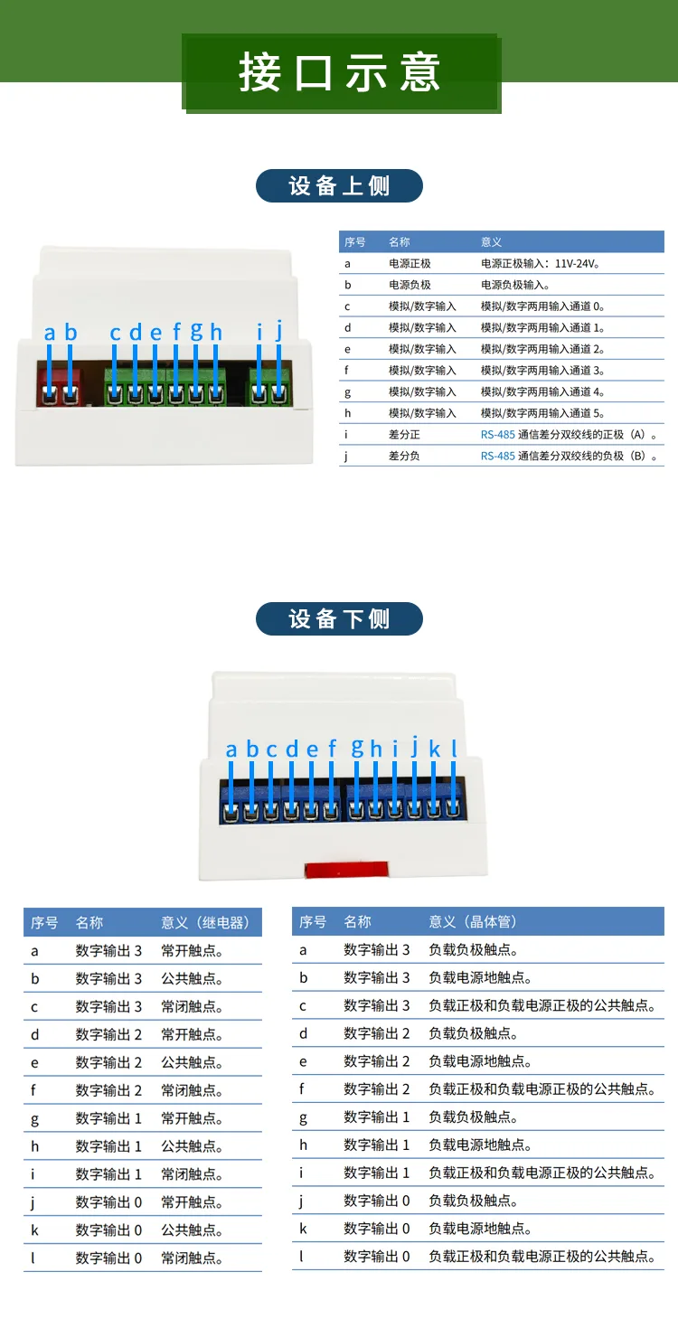
The I/O set is deliberately generous for the footprint. Six input channels each accept a dry contact or an analog voltage up to 35 V DC, so transmitters land directly without an AI card (note the inputs share the module's 0 V rail — they are not isolated from the supply). Four output channels switch up to 8 A each: the relay variant offers potential-free NO-COM-NC contacts for 0–30 V DC or 0–220 V AC loads and drives an AC contactor coil directly, while the transistor variant covers fast-switching 12–48 V DC loads.
Field protection is engineered rather than assumed: reverse-polarity diode, transient suppressor and self-resetting fuse on the supply; branded output relays with a dedicated arc-absorption element that rides out the ~400 Vp-p spike of a dropping contactor; and tested 4 kV ESD / 2 kV EFT immunity. One boundary is non-negotiable — this is not a safety controller. E-stops, guard doors and light curtains belong on a DQSRN or DA31 safety relay module.
Logic Flow Concept
Technical Specifications
| Type | Multi-functional programmable delay / logic module (micro PLC class), graphical schematic programming |
|---|---|
| Supply | 11–24 V DC, reverse-polarity protected, 28 V absolute max; ≤ 250 mA running, ≤ 35 mA standby |
| Inputs | 6 channels, digital or analog, 0–35 V DC, non-isolated from supply (field devices share the 0 V rail) |
| Outputs | 4 channels, relay or transistor by model |
| Relay output | Potential-free NO-COM-NC changeover, 0–30 V DC or 0–220 V AC, max 8 A |
| Transistor output | Sinking, 12–48 V DC only (no AC), max 8 A |
| Communication | B/A terminals, RS-485 or TTL selectable, Modbus networking to PLC / HMI / gateway |
| Options | RTC real-time clock (scheduled operation); wireless remote control. Standard build: digital input + relay output + RS-485 |
| Isolation (tested) | Relay output side 1000 V DC; input side 1500 V DC; creepage ≥ 6 mm and clearance ≥ 2 mm, relay terminals to logic side, pollution degree 3 |
| EMC (IEC 61000-6-1-2006) | ESD 4 kV normal operation on all input/power terminals; EFT 2 kV/5 kHz normal operation, 4 kV without damage (wireless/RTC options may briefly deviate at 4 kV) |
| Ambient | Operating −20 to +60 °C; storage −40 to +80 °C |
| Dimensions | 72 × 88 × 59 mm (L × W × H) |
Relay life-cycle rating, IP rating and RTC drift figures are not published for this model — request the current datasheet rather than assuming values from sibling modules.
Typical Applications
Non-Standard Machine Sequencing
Start/stop chains, limit interlocks and fault lockouts on packaging, filling and cleaning machines — drawn once, downloaded, and revised without touching panel wiring.
Pump, Fan & Tank Automation
Level and pressure switches drive multi-pump rotation and refill logic; add the RTC option for off-peak scheduling windows.
Lighting & Building Schedules
Streetlights, signage and landscape circuits switch by RTC clock or by light-level triggers, with the wireless remote option covering retrofit sites without control cabling.
Sensor-Threshold Interlocks
Temperature, humidity or pressure transmitters wire straight into the analog-capable inputs; threshold comparisons start heaters, fans or valves — no separate AI card.
RS-485 Edge Logic Node
Runs its own logic locally while reporting I/O states over Modbus to a host PLC or HMI, so the machine keeps working when the network does not.
Frequently Asked Questions
Where does the D4G0206 fit between a timer relay and a real PLC?
A fixed-function timer gives you one behavior per part; a full PLC gives you unlimited logic at the cost of rail space, price and ladder programming. The D4G0206 occupies the middle: 6 inputs and 4 outputs of freely drawable logic in a 72 × 88 × 59 mm housing, with Modbus networking — enough for most small-machine and utility sequencing without a PLC engineer on the payroll.
What does 'schematic programming' actually look like?
You place function blocks (logic gates, timers, counters) on a canvas in the host-PC software, wire them with the mouse the way you would draw a circuit diagram, then download the drawing to the module through the B/A terminals. No ladder logic and no code — a technician who can read a flowchart can maintain the program.
Relay output or transistor output — how do I choose at order time?
Order the relay version for AC contactor coils, solenoid valves and mixed loads: each channel is a potential-free changeover contact handling 0–30 V DC or 0–220 V AC at up to 8 A. Order the transistor version for DC-only loads that switch frequently: sinking outputs, 12–48 V DC, also 8 A, with no AC permitted. The logic platform, terminals and your drawn program stay identical either way.
Can it operate on a time-of-day schedule or be triggered without cables?
Both are order-time options. The RTC (real-time clock) option adds fixed start/stop times and time-segmented operation such as off-peak running; the wireless remote option adds cable-free local triggering, which retrofit lighting and agricultural sites typically need. The standard build is digital input + relay output + RS-485.
How robust is it electrically?
The supply input carries reverse-polarity, transient-suppression and self-resetting overcurrent protection on an 11–24 V DC rail (28 V absolute max). Per IEC 61000-6-1-2006 testing, all input and power terminals withstand 4 kV ESD and 2 kV/5 kHz EFT with normal operation. The relay outputs use branded relays with a dedicated arc-absorption component, and the relay side is isolation-tested to 1000 V DC with ≥ 6 mm creepage to the logic side.
Can I use it for an emergency stop or guard-door circuit?
No. The D4G0206 carries no Type, SIL or PL rating; it is general-purpose logic, and its outputs are not OSSDs. Machine safety functions must run through certified safety logic — pair your E-stop, curtain or interlock with a DQSRN or DA31 safety relay module and keep the D4G0206 on the process side of the circuit.
What about MOQ, samples and OEM arrangements for export?
Evaluation samples are available so your team can trial the drawing software against a real application before committing. Volume pricing, OEM labelling and option pre-configuration (RTC / wireless / output type) are agreed per order; lead time depends on the option mix, so state it in your enquiry for a current schedule.